
Design an anodized heat sink extrusion by developing its cross-section, material condition, machining allowances, finish boundaries, and assembly tests together. A tall fin profile may fit your thermal model yet emerge twisted, need excessive machining, or restrict the airflow available inside your equipment. Review those constraints before ordering a die, then qualify representative finished parts against the operating conditions that matter to your design.
1. How is an anodized heat sink extrusion manufactured?
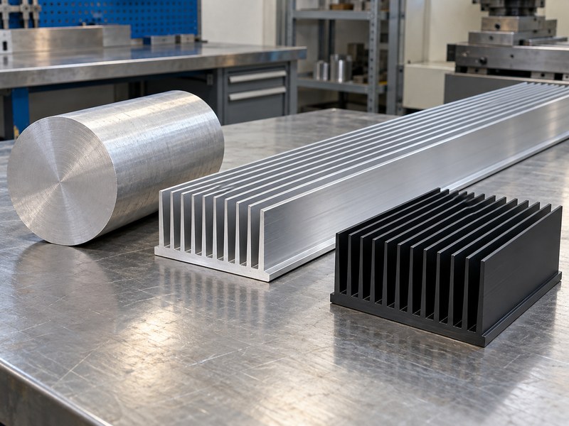
An anodized heat sink extrusion starts as a heated aluminum billet forced through a shaped die, then undergoes the cooling, dimensional correction, cutting, machining, and finishing required by its production plan. The die establishes the continuous cross-section. Local mounting pockets and holes usually need later operations, so a profile drawing alone does not describe the delivered component.
Which stages need their own acceptance conditions?
Distinguish the raw profile, cut blank, machined part, and finished assembly in your documentation. Each stage introduces a different inspection question: cross-sectional dimensions, cut length, interface geometry, or coating coverage. State where dimensions apply instead of letting an inspector compare a finished coated part with limits intended for raw stock. When a defect appears, this sequence also helps your team investigate the operation that created it.
- Identify the extrusion direction on the drawing.
- Separate continuous features from local machined details.
- Define acceptance at each delivered condition.
| Production stage | Feature to control |
|---|---|
| Extrusion | Continuous base and fin cross-section |
| Fabrication | Length, holes, pockets, and contact face |
| Finishing | Coating coverage and functional boundaries |
Approve a process route that reaches the drawing’s final condition.
2. Which alloy and temper belong in the process plan?
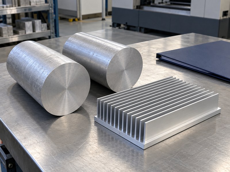
The alloy and temper for an anodized heat sink extrusion should satisfy heat spreading, extrudability, mounting strength, machinability, and finish requirements together. A series designation alone leaves the delivered material condition unresolved. Select a specific grade and condition with the extrusion team, using properties appropriate to the final part rather than treating every aluminum alloy as interchangeable.
What should the material review establish?
Heat-treatable extrusion alloys depend on a controlled thermal history to reach their specified condition. Document the agreed route and material verification without inventing a universal billet temperature or aging cycle for every profile. A conductivity preference can conflict with a thin fin geometry or a heavily loaded mounting feature. Resolve that conflict on the drawing, including whether a proposed substitute needs another forming, machining, or appearance review.
- Identify alloy, temper, and material acceptance requirements.
- Review mechanical loads at mounting features.
- Approve substitutions against the complete part specification.
| Material question | Evidence to request |
|---|---|
| Will it spread heat? | Conductivity information for the relevant condition |
| Will it support the assembly? | Mechanical requirements and material verification |
| Will it finish consistently? | Representative anodized material samples |
Keep the material designation connected with its processing and acceptance records.
3. How should the die balance metal flow across the profile?
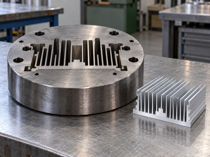
The die for an anodized heat sink extrusion should control metal flow so the base and fins emerge with compatible movement and usable geometry. Thick and thin regions place different demands on that flow. The die designer can adjust tooling features, but a severely unbalanced cross-section may also need a product-design change rather than repeated tool correction.
Which geometric compromises deserve discussion?
Review abrupt thickness changes, narrow gaps, asymmetry, and unsupported tooling features before finalizing the profile. Generous transitions can support extrusion feasibility, provided they preserve the required contact area and airflow passage. Integrated heat sink enclosures add rails, walls, and mounting details that should enter the same cross-sectional review. Ask which departures are needed for stable production and record them explicitly; a nominal CAD surface should not silently become an approximate feature.
- Discuss metal-flow balance with the die designer.
- Mark radii and tapers that affect functional clearance.
- Approve tool-driven changes before trial extrusion.
| Profile feature | Tooling question |
|---|---|
| Thick base and thin fins | Can their exit behavior be balanced? |
| Deep narrow gaps | Is the supporting die geometry practical? |
| Asymmetric mounting rail | How will distortion be controlled? |
Resolve the cross-section before approving detailed downstream machining.
4. What limits fin height, thickness, and pitch?
Fin height, thickness, and pitch in an anodized heat sink extrusion are limited by the proposed alloy, tooling, press capability, profile size, and required dimensional consistency. A published fin ratio describes a particular capability rather than automatic approval of your drawing. Define which dimensions the ratio uses, since height-to-thickness and height-to-gap describe different geometric relationships.
How do you avoid designing around an ambiguous ratio?
Give the extrusion team a dimensioned cross-section with clear fin gaps, root radii, tip geometry, and base thickness. Ask for feasibility at the requested tolerances and delivered condition. A thin, tall fin can provide additional area while creating handling and straightness concerns; it may also conduct less effectively toward its tip. Compare practical candidate sections instead of adding fins until the available envelope looks full.
- Define fin thickness and gap independently.
- Include root transitions in the airflow model.
- Identify which dimensions need tighter control.
| Dimension | Coupled design concern |
|---|---|
| Fin height | Area, conduction, handling, and tooling |
| Fin thickness | Fin conduction and achievable geometry |
| Fin pitch | Fin count and available air passage |
Select the geometry that meets both manufacturing and thermal requirements.
5. How should fin spacing match the available airflow?
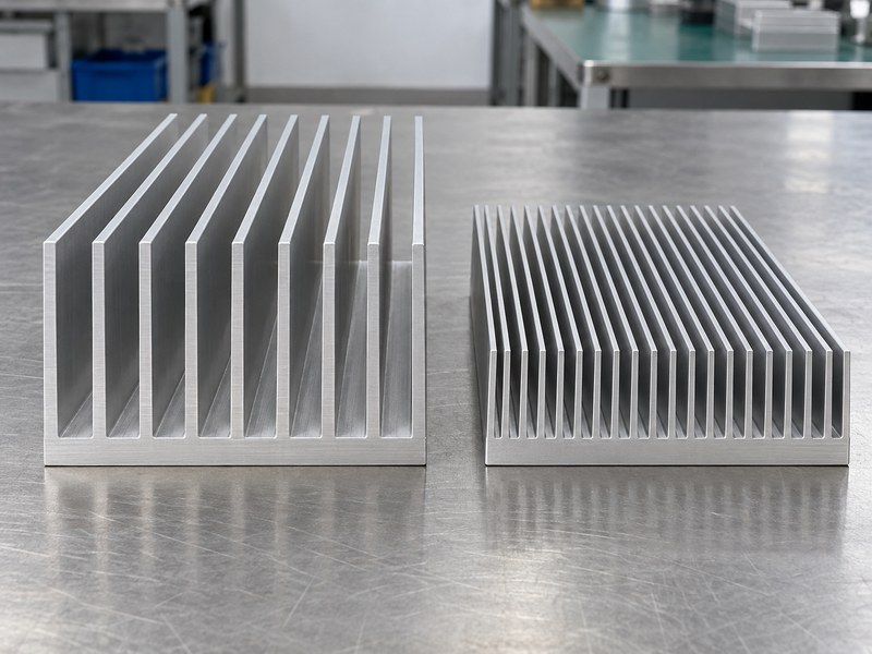
Fin spacing in an anodized heat sink extrusion should match its convection mode, fin length, installation orientation, and available pressure or buoyancy-driven flow. Natural convection needs passages that let warm air rise and replacement air enter. A fan can support a different spacing, but a dense array may create enough resistance to reduce the installed airflow.
What should your airflow comparison include?
Compare candidate profiles inside the intended duct, housing, or surrounding clearance. Include bypass around the fins and use the fan’s response to system resistance rather than its free-air flow rating alone. Passive arrangements need realistic gravity orientation and unobstructed inlet and outlet paths. Changes that increase metal area can still raise device temperature when they reduce useful air movement, so evaluate temperature and flow together.
- Record orientation and surrounding obstructions.
- Compare candidate gaps under the same boundary conditions.
- Check fouling and cleaning access where relevant.
| Cooling mode | Question for the installed design |
|---|---|
| Natural convection | Can buoyant air enter and leave the channels? |
| Forced airflow | What flow remains against system resistance? |
| Restricted enclosure | Where does air bypass or recirculate? |
Evaluate the profile at its installed operating point.
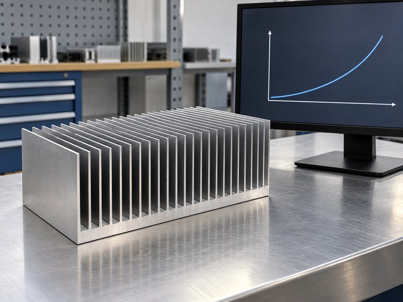
6. How do cooling and straightening affect usable geometry?
Cooling and straightening affect the bow, twist, and dimensional condition of an anodized heat sink extrusion before it becomes a short finished part. The required process depends on material and profile geometry. Long-stock straightness, local contact-face flatness, and finished-part alignment answer different questions, so specify the condition and measurement length associated with each requirement.
Why should you inspect beyond the long stock?
A long profile that meets its agreed straightness limit may still need machining at the device contact. Cutting, workholding, and later material removal can change the geometry of a short blank. Measure representative parts after those operations instead of assuming the raw-stock report proves the final interface. If a locating surface is established during machining, use that datum consistently when checking mounting features and the delivered contact face.
- State inspection support and measurement length.
- Separate global straightness from local face flatness.
- Inspect again after operations that can change geometry.
| Geometry requirement | Inspect in this condition |
|---|---|
| Stock bow or twist | Agreed profile length and support |
| Blank alignment | After cutting and required correction |
| Contact-face flatness | Final functional condition |
Base acceptance on the surface condition your assembly will receive.
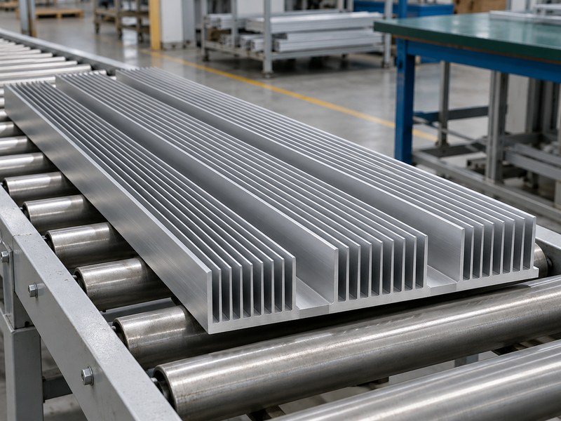
7. Which operations establish the final mounting interface?
Cutting, machining, deburring, and controlled workholding establish the final mounting interface of an anodized heat sink extrusion when the raw profile cannot meet the assembly requirement directly. Define the device footprint, mounting datums, and finished contact condition before choosing machining allowances. Removing extra material later cannot reliably repair every distortion or an inaccessible mounting feature.
How should machining relate to the profile drawing?
Locate holes and contact surfaces from functional datums instead of an uncontrolled fin tip. Support the base during machining and handling so clamping does not bend delicate fins. Review CNC machined heat sinks when pockets or local geometry exceed what the continuous profile provides. Specify burr removal at cut ends and threaded features, including where loose chips could remain trapped between fins or prevent an interface pad from seating.
- Reserve material where a finished contact face requires it.
- Keep tool and workholding access in the design review.
- Define finished dimensions after the required operations.
| Interface feature | Fabrication control |
|---|---|
| Device contact face | Datum, flatness, and surface condition |
| Mounting hole | Position and finished fit |
| Cut end or thread | Burr and chip removal |
Inspect the delivered interface rather than accepting it from profile dimensions alone.
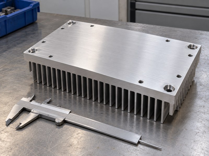
8. When should machining, masking, and anodizing occur?
The process plan for an anodized heat sink extrusion should place machining, masking, and anodizing in a sequence that preserves each functional surface. Machining commonly establishes precision features before finishing, while selected contact faces or electrical lands may require masking. Any deliberate cut after anodizing exposes metal that needs a defined acceptance and environmental plan.
Which surfaces require separate instructions?
Distinguish exposed fins, thermal contact faces, grounding lands, threads, and appearance zones on a finish map. Agree rack-contact locations and inspection access within deep channels. Oxide on a contact face changes the interface stack; an attractive black surface cannot establish its thermal resistance or safety insulation. Approve representative complete parts so cleaning, rinsing, coating boundaries, and finished fits receive attention alongside color.
- Mark masking boundaries on the drawing.
- Identify permissible rack marks and handling contact.
- Verify fits and interfaces after surface treatment.
| Surface group | Sequence decision |
|---|---|
| Exposed fins | Coverage, cleanliness, and appearance |
| Device contact face | Machining and masking condition |
| Electrical or threaded interface | Conductivity or finished-fit requirement |
Keep finish approval tied to the delivered surface map and functional checks.
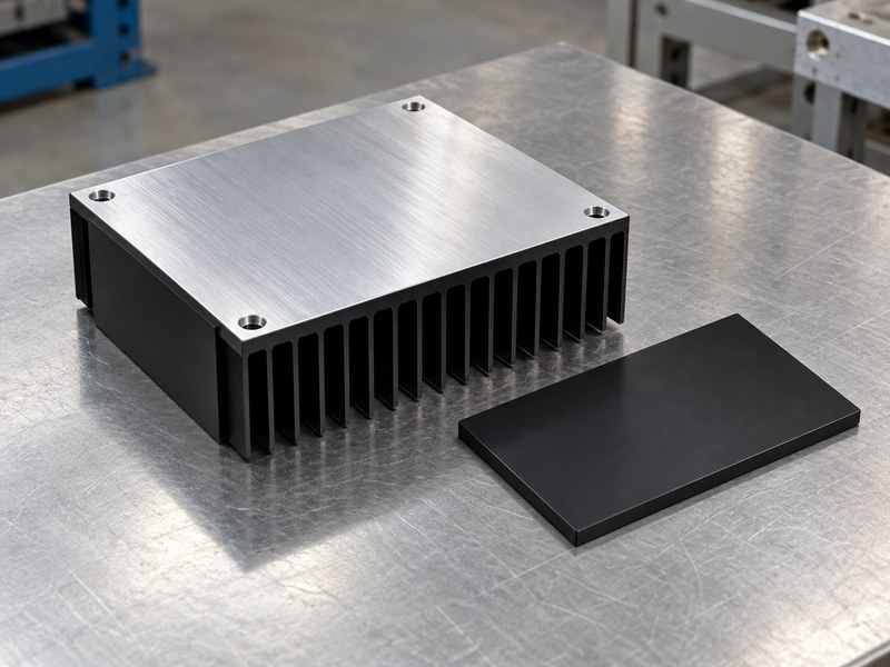
9. What should a representative trial run demonstrate?
A trial run should demonstrate that an anodized heat sink extrusion can meet its geometry, material, machining, and finish requirements across representative production samples. One attractive cut section leaves variation along the run unresolved. Agree sample locations and inspection scope around the features most likely to affect mounting, airflow, appearance, or repeat assembly.
How do you make trial results useful for production?
Connect measurements with the die revision, material condition, and processing route used for those samples. Compare fin gaps, local straightness, contact-face condition, and finished mounting features without selecting only the best-looking pieces. Evaluate heat sink mounting hardware with the actual interface stack where clamp loading affects fit or thermal contact. Record deviations and accepted corrective actions before releasing the drawing, so later batches have a usable reference beyond photographs.
- Identify samples and their relevant production conditions.
- Check difficult features and allowed handling marks.
- Define which changes require renewed qualification.
| Trial evidence | Production decision it supports |
|---|---|
| Dimensional results | Achievable geometry and inspection points |
| Material and finish records | Delivered condition and traceability |
| Assembly checks | Fit, contact, and handling acceptance |
Use the trial to settle acceptance limits and process controls before release.
10. How do you approve the extrusion for its application?
Approve an anodized heat sink extrusion when representative finished parts meet the drawing and the assembled equipment meets its thermal requirements under defined operating conditions. Geometry acceptance alone cannot establish cooling capability. Reproduce heat input, source footprint, interface material, mounting load, airflow, orientation, and surrounding temperatures closely enough to test the design assumptions behind the selected profile.
What should remain with the released drawing?
Keep the approved material condition, cross-section, finish map, machining details, and test configuration together. State whether a reported thermal resistance belongs to the sink, a device interface, or a complete assembly. Include sensor locations and uncertainty when a small temperature difference drives acceptance. When a profile or installation changes, review which evidence still applies instead of carrying a previous temperature result forward without checking its conditions.
- Retain the accepted sample and process revisions.
- Connect thermal results with the tested configuration.
- Review geometry, finish, or airflow substitutions before use.
| Release record | What it must identify |
|---|---|
| Functional drawing | Material, datums, finished dimensions, and surfaces |
| Manufacturing approval | Representative samples and accepted deviations |
| Application validation | Heat load, mounting, environment, and results |
Send your cross-section, heat-source layout, operating conditions, and mounting requirements when you contact us. Include existing test evidence so the engineering review can address the remaining geometry and process decisions.
FAQ
Q1: Can I reuse one extrusion die for different cut lengths?
Often, if the cross-section remains suitable. Each length still needs a review of mounting, machining access, airflow, and thermal performance; sharing a die does not establish a shared cooling rating.
Q2: What’s the best fin ratio to put on my drawing?
Use explicit dimensions instead of an unexplained ratio. State fin height, thickness, and clear gap, then ask the extrusion team to review that geometry at the required tolerances.
Q3: Can I use a dense fan-cooled profile without its fan?
Only after validating the passive operating condition. The remaining passages, orientation, and clearances must support buoyancy-driven flow at the required heat load and ambient temperature.
Q4: How do I know if the base needs machining?
Compare its delivered geometry with the interface requirement. Check flatness, texture, clamp load, and interface-material behavior before deciding whether the raw profile provides an acceptable mounting surface.
Q5: Can I approve the finish on a small flat coupon?
Use it for limited process or appearance comparisons. A complete representative part is still needed to inspect deep channels, masking boundaries, rack marks, and functional fits that the coupon does not reproduce.