
Specify a machined anodized aluminum heat sink by connecting its datums, accessible geometry, finished dimensions, and contact condition with your assembly requirements. A sample can look clean yet rock on its mounting surface, bind at a coated thread, or leave an interface pad spanning the wrong gap. Define those interfaces before approving the machining and finishing sequence, then check representative completed parts rather than relying on appearance alone.
1. What defines a machined anodized aluminum heat sink?
A machined anodized aluminum heat sink combines material-removal operations that establish required features with a separately specified anodic surface treatment. Its starting form may be plate, an extrusion, or another suitable aluminum blank. The term describes two processing stages; it does not establish alloy, dimensional tolerance, coating coverage, electrical behavior, or a proven cooling rating.
Which features need a functional description?
Identify what each machined face does in the assembled product. A contact pad receives heat, a locating shoulder controls position, and a threaded mounting feature carries an assembly load. These surfaces can require different finishes and inspection methods even when they belong to one part. Mark them on the drawing so the machining and finishing teams can discuss the same interfaces instead of interpreting a blanket note independently.
- Identify the heat-source footprint and mounting features.
- Name the supplied material and final condition.
- Separate surface appearance from functional acceptance.
| Feature group | Requirement to establish |
|---|---|
| Contact face | Thermal interface and geometry |
| Mounting feature | Position, fit, and load path |
| Exposed surface | Finish, appearance, and environment |
Use the part’s functions to organize its manufacturing requirements.
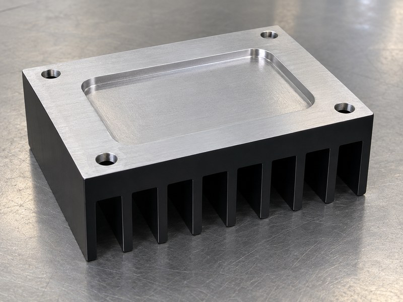
2. Which datums should locate the source and mounting holes?
Datums for a machined anodized aluminum heat sink should reflect how the device and surrounding assembly locate the part. Select stable, inspectable reference features that connect the contact region, hole pattern, and locating surfaces. An uncontrolled fin tip or rough cut edge can make convenient shop contact while providing a poor reference for the functional geometry.
How do you connect inspection with assembly?
Describe the intended reference plane and locating directions in the drawing’s datum scheme. Make the mounting pattern and contact feature relate to those references rather than accumulating unrelated edge dimensions. Review whether finishing changes a selected datum surface and state its final condition. When inspection needs a particular support arrangement, document it so a compliant measurement represents the same geometry your assembly depends on.
- Locate functional holes from agreed datum features.
- Define whether datum faces are coated or masked.
- Keep setup references consistent across relevant operations.
| Reference feature | Assembly relationship to control |
|---|---|
| Supporting plane | Contact and mounting orientation |
| Side or locating feature | Lateral device position |
| Hole pattern | Fastener and bracket alignment |
Choose references that both production and assembly can reproduce.
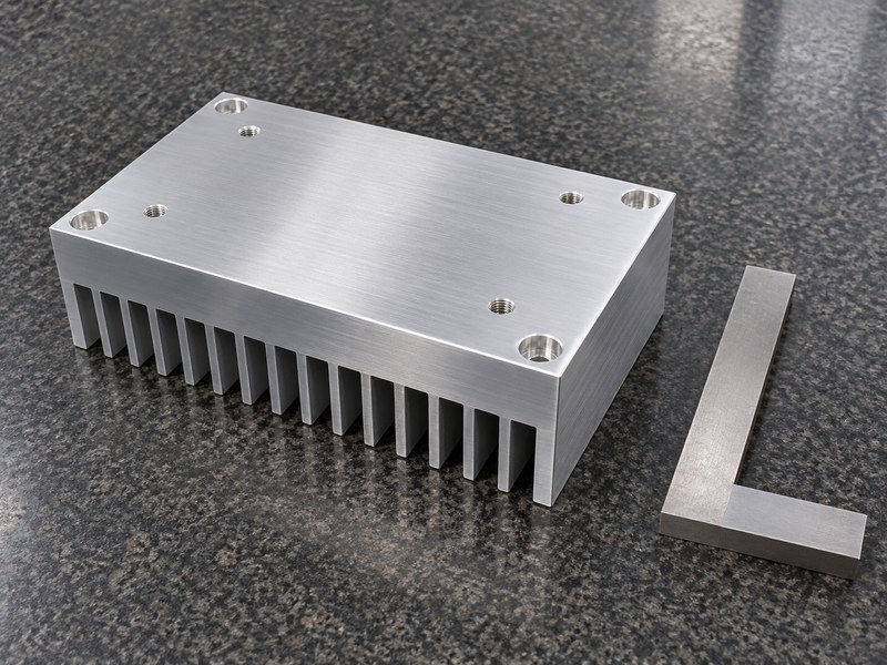
3. How should tool access shape pockets and internal corners?
Tool access should shape the pocket depths, corner radii, approach directions, and undercuts of a machined anodized aluminum heat sink. A feature visible in CAD may be unreachable with a practical cutter and holder. Review access before freezing adjacent fins or walls, since a small geometric change may remove the need for an awkward secondary setup.
Which details should you give the machining team?
Show the mating component’s envelope so the team can distinguish required clearance from unnecessary sharp corners. A rotating cutter leaves an internal radius; agree a compatible radius or another manufacturing route where the assembly needs a sharper feature. In heat sink enclosures, surrounding walls and connector openings can restrict tool and inspection access together. Consider how the finished feature will be measured as well as how it will be cut.
- Check holder clearance around nearby fins and walls.
- Identify undercuts and hidden contact surfaces.
- Allow practical corner radii where function permits.
| Geometry detail | Access question |
|---|---|
| Deep narrow pocket | Can a suitably stiff tool reach it? |
| Internal corner | What radius will clear the mating part? |
| Recessed mounting feature | Can machining and inspection reach it? |
Resolve access constraints before assigning a tight tolerance to the feature.
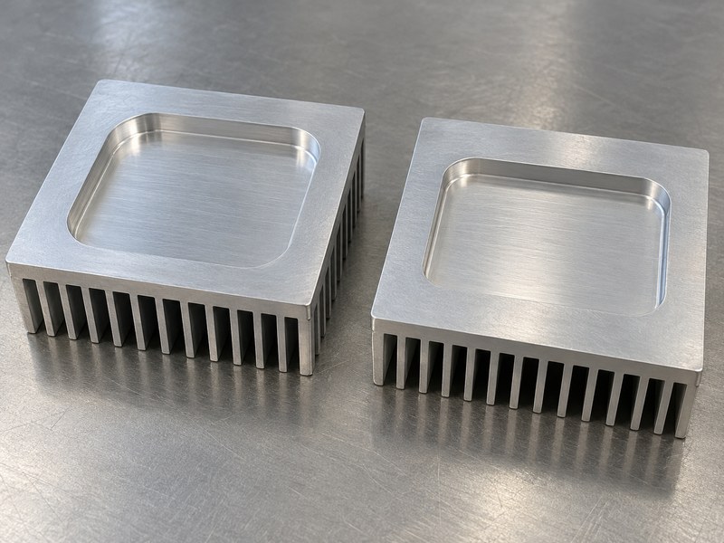
4. How do thin walls and base geometry affect machining?
Thin walls and a lightly supported base can deflect during machining, changing the geometry of a machined anodized aluminum heat sink after the cutting or clamping load is removed. Pocket depth, remaining material, and workholding belong in the same review. A visually efficient shape may leave too little stiffness for repeatable contact-face or mounting-feature control.
Where should you preserve stiffness?
Review the material remaining beneath pockets and between mounting features rather than looking only at the outside envelope. The machining team may need a different sequence, support location, or stock allowance to control movement. Keep clamps away from fragile fins and identify surfaces that can accept handling contact. Any geometry added for stiffness also changes mass and the heat path, so reconcile manufacturing changes with the thermal model before release.
- Review wall and base stiffness after material removal.
- Agree which surfaces can receive workholding loads.
- Inspect critical geometry after unclamping as specified.
| Geometry choice | Coupled effect to review |
|---|---|
| Deep pocket | Reduced support and tool reach |
| Thin base region | Deflection and heat spreading |
| Mounting flange | Clamping access and assembly stiffness |
Approve the finished geometry in the condition your drawing defines.
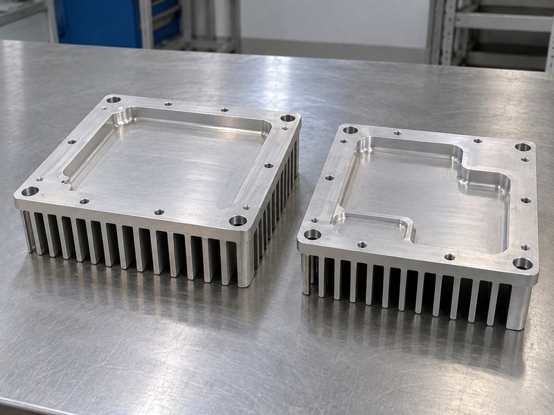
5. What controls burrs, chips, and fragile fin edges?
A defined cutting, deburring, cleaning, and handling plan controls burrs and loose chips on a machined anodized aluminum heat sink. Anodizing should not be expected to remove every machining defect. Pay attention to hole exits, thread starts, pocket edges, and cut fin ends where unwanted metal can obstruct assembly, damage an interface material, or detach during handling.
How specific should edge requirements be?
Identify edges whose geometry affects seating, electrical clearance, or a mating component. Agree a deburring method that removes unwanted material without rounding a controlled locating edge beyond its requirement. Inspect difficult recesses and spaces between fins after cleaning rather than checking only the broad contact face. Protect thin fins during transport between operations, because a part can acquire bent tips or impact damage after acceptable machining.
- Mark functional edges that need controlled treatment.
- Check holes, threads, and recesses for retained chips.
- Keep contact faces protected during internal handling.
| Location | Defect to prevent |
|---|---|
| Hole exit or thread start | Burr that obstructs fastening |
| Contact-pad boundary | Raised material that affects seating |
| Fin channel | Retained chips or handling damage |
Define acceptable edges before the sample becomes the informal standard.
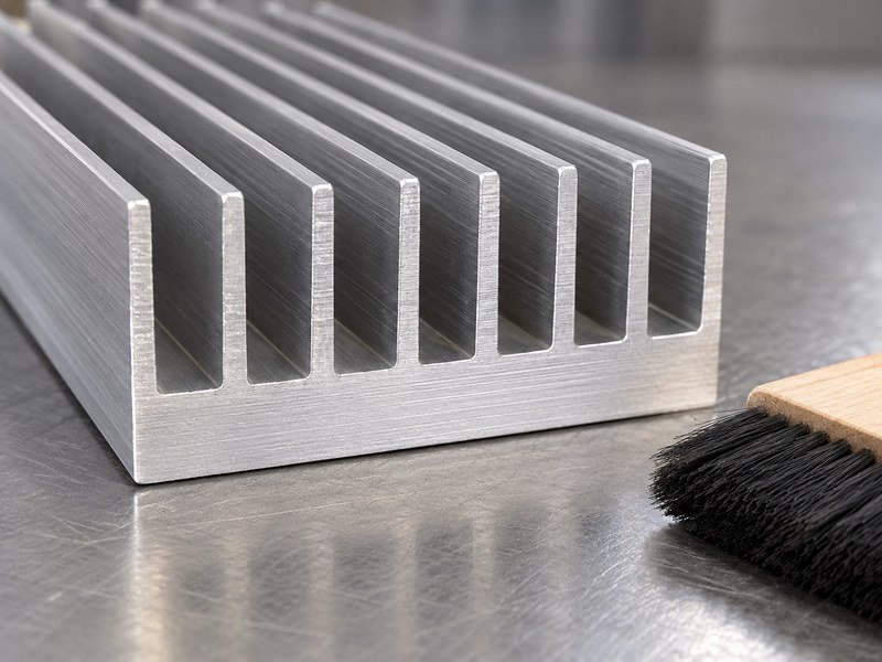
6. Should machining happen before or after anodizing?
Choose the machining and finishing order for a machined anodized aluminum heat sink from its functional surfaces and exposure requirements. Machining before anodizing lets the specified finish reach selected completed features. Machining afterward deliberately removes coating from cut surfaces, which may serve a contact requirement but also creates exposed-metal boundaries and additional handling considerations.
What does each sequence leave unresolved?
A machine-then-anodize route still needs masking, dimensional allowances, cleaning, and appearance acceptance. The oxide does not guarantee that tool marks disappear or that every recessed surface receives an identical finish. An anodize-then-machine route needs agreement on bare cuts, edge quality, and protection of the existing coating during workholding. Compare the delivered interfaces of both routes instead of treating either order as automatic proof of a flawless part.
- Map the surfaces altered by each operation.
- Approve exposed cuts and their environmental treatment.
- Check appearance on representative finished geometry.
| Sequence | Requirement to resolve |
|---|---|
| Machine before anodizing | Masking, allowance, and final fits |
| Machine after anodizing | Bare cuts and coating protection |
| Mixed local processing | Boundaries and final inspection stage |
Record the selected sequence with the drawing’s finished-surface requirements.
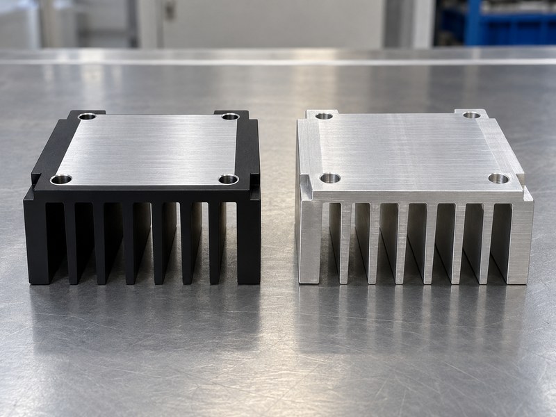
7. How should masking preserve threads, bores, and bond pads?
Masking on a machined anodized aluminum heat sink should preserve specified functional regions while leaving coating boundaries that production can inspect. Anodizing and its pretreatment can change dimensions, so a tight bore or thread needs a delivered-condition requirement. Decide with the finisher whether masking, an agreed machining allowance, or another controlled sequence suits the actual feature.
Which interfaces need separate instructions?
Mark thread depth, bore limits, grounding lands, and thermal-contact zones individually where their requirements differ. A bare grounding pad needs a defined conductive joint and an exposure plan; incidental contact through oxide does not establish repeatable bonding. Review heat sink mounting hardware with the finished thread and seating surfaces. Do not apply one coating-growth allowance to every feature without agreement on the actual process and acceptance method.
- Show masking boundaries and allowed boundary variation.
- Verify finished threads with the agreed inspection method.
- Define protection for exposed functional aluminum.
| Interface | Requirement after finishing |
|---|---|
| Precision bore | Delivered fit and surface condition |
| Threaded mounting hole | Usable fit and engagement |
| Grounding land | Controlled conductive connection |
Judge each masked region by its function and final condition.
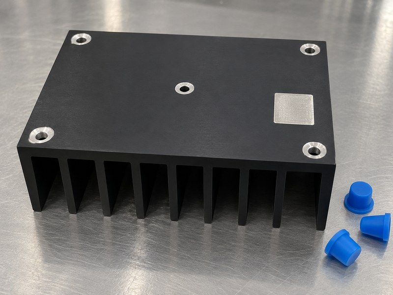
8. How do you specify contact flatness and interface gaps?
Specify contact flatness and gaps for a machined anodized aluminum heat sink from the device footprint, mounting stack, interface material, and available clamp load. A smooth-looking face can still leave a poor contact pattern. Evaluate the oxide, exposed metal, surface texture, and actual gap together rather than assuming the finish has a negligible thermal effect in every assembly.
What should the interface review compare?
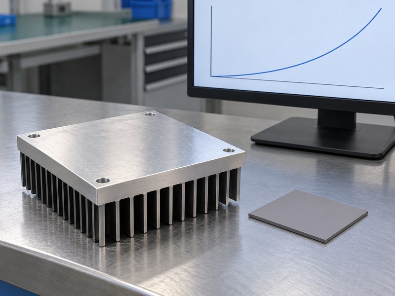
Distinguish overall part flatness from the local contact region that receives device heat. Include tolerances of nearby standoffs or shoulders that can hold the sink away from the source. Select thermal pads against the assembled gap and permitted compression, then check the force the mounting system can provide without overstressing the device. A thicker interface may accommodate variation while adding resistance, so verify the resulting temperature in the assembled condition.
- Mark the active contact footprint on the drawing.
- Review the complete dimensional stack and clamp path.
- Control interface thickness and assembly method during tests.
| Interface variable | Check needed |
|---|---|
| Local face geometry | Seating across the source footprint |
| Mechanical stack | Remaining gap after assembly |
| Interface material | Compression, thermal behavior, and load |
The conceptual curve below illustrates an interface tradeoff rather than measured thermal resistance or a product prediction.
9. Which inspections belong after the final operation?
Inspect a machined anodized aluminum heat sink after the operations that can change the characteristic you need to accept. Final contact geometry, thread fit, masking boundaries, coating condition, and cleanliness cannot all be established by an early machining report. Specify the relevant inspection stage so a measurement taken before finishing does not silently stand in for delivered-part evidence.
How do you make a report traceable to the part?
Connect inspection results with the drawing revision, sample identity, and agreed process route. State the datum setup and measurement method where they affect interpretation, especially for recessed faces or parts that can flex under support. Keep dimensional, finish, and appearance checks distinct enough to identify which requirement failed. A photograph can document a defect or approved appearance, but it cannot establish flatness, thread fit, or a thermal contact condition by itself.
- Record actual results for controlled characteristics.
- Identify approved deviations before shipment acceptance.
- Preserve sample identity through finishing and inspection.
| Acceptance group | Useful final evidence |
|---|---|
| Functional geometry | Datum-based dimensional results |
| Surface condition | Finish, masking, and edge inspection |
| Assembly readiness | Fit and cleanliness checks |
Require evidence from the delivered condition for each acceptance decision.
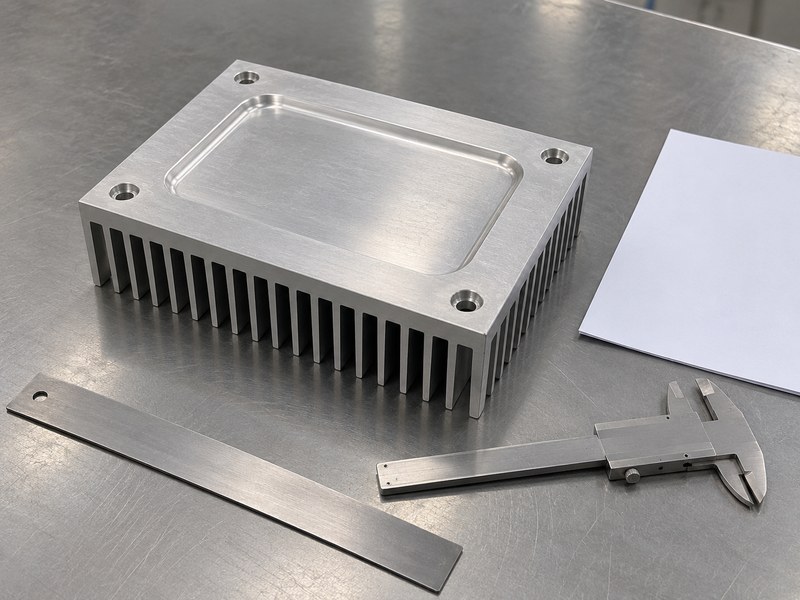
10. How do you approve a small batch for assembly?
Approve a small batch of machined anodized aluminum heat sink parts by checking representative finished parts against the drawing and assembling them with the intended interface and hardware. A single hand-adjusted sample may hide a fit problem that returns in the next piece. Agree which characteristics need individual checks and which can use a justified sampling plan.
What should approval establish before repeat supply?
Record whether the sample uses the proposed production material, machining sequence, masking, and finish. Inspect additional pieces where variation in a contact face, hole position, or thread fit could affect interchangeability. Test thermal operation with documented power, airflow, ambient temperature, and mounting conditions instead of converting dimensional approval into a cooling claim. Keep any accepted rework visible so a later order reproduces the agreed process rather than the appearance of a specially prepared sample.
- Resolve assembly interference before releasing the batch.
- Retain an approved sample and its inspection record.
- Review changes to material, machining, or finishing.
| Approval item | Agreement to retain |
|---|---|
| Part definition | Drawing, material, and process revisions |
| Interchangeability | Fit checks and relevant sample results |
| Thermal operation | Tested assembly and operating conditions |
Send your model, dimensioned drawing, mating-part information, and finish map when you contact us. Include your interface gap and mounting limits so the review can address manufacturing access and delivered-part acceptance together.
FAQ
Q1: Can I machine a contact pad after anodizing?
Yes, with an agreed process and acceptance plan. Specify the bare area, protect the surrounding coating, remove burrs, and address corrosion exposure at the newly machined surface.
Q2: What’s the best tolerance for the mounting face?
Use the tolerance required by the complete interface. Device footprint, surface texture, pad behavior, clamp load, and assembly stack determine whether a proposed face condition is adequate.
Q3: Can I leave every threaded hole unmasked?
Only when the finished fit meets the requirement. Coating and pretreatment affect dimensions, so agree the process with the finisher and inspect usable threads after the relevant operations.
Q4: How do I know if a pocket can be machined reliably?
Request a review of tool access, corner radii, remaining stiffness, and workholding. Include the mating component and inspection requirement so a reachable cut also produces a usable feature.
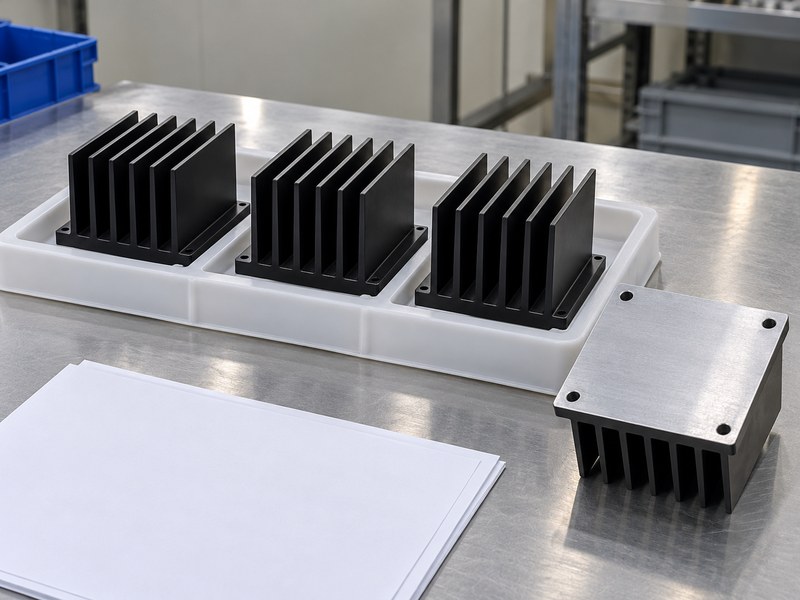
Q5: Can I approve the batch from its black appearance?
Use appearance as one acceptance check. Inspect the delivered contact geometry, fits, masking, cleanliness, and assembly behavior separately before treating the batch as ready for use.