
Choose a copper tube heat sink by matching its sealed or pumped architecture, source contact and cooling boundary to your equipment. The tube may be a sealed heat pipe or a passage for pumped coolant. If your drawing leaves that distinction open, suppliers can quote assemblies with different operating requirements. Define the transport method, contact joints and final heat rejection boundary before choosing tube dimensions.
1. Which copper tube heat sink architecture do you need?
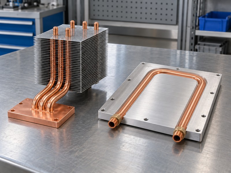
Choose the architecture by identifying whether heat must reach local airflow or an external liquid circuit. A copper tube heat sink with sealed heat pipes recirculates its internal working fluid without external plumbing. A tube-in-plate assembly carries pumped coolant through an inlet and outlet, then depends on the rest of the liquid loop to reject that heat.
Trace both ends of the thermal path
Ask for a section drawing rather than judging a copper tube by its appearance. A bent tube disappearing into aluminum can represent either architecture, but the required validation differs. Check the actual source position, available condenser area and destination temperature before discussing tube count. An attractive pipe route cannot compensate for a fin stack sitting in stagnant enclosure air.
- Identify sealed ends or external fluid connections.
- Mark where heat enters and leaves the tube.
- Define the final air or coolant temperature reference.
| Architecture | External dependency | Approval focus |
|---|---|---|
| Sealed heat pipe | Cooler condenser | Transport and attitude |
| Pumped tube | Flowing coolant loop | Flow, pressure and leakage |
Specify the architecture explicitly whenever a procurement drawing uses the broad term “copper tube.”
2. Why use copper where heat enters the assembly?
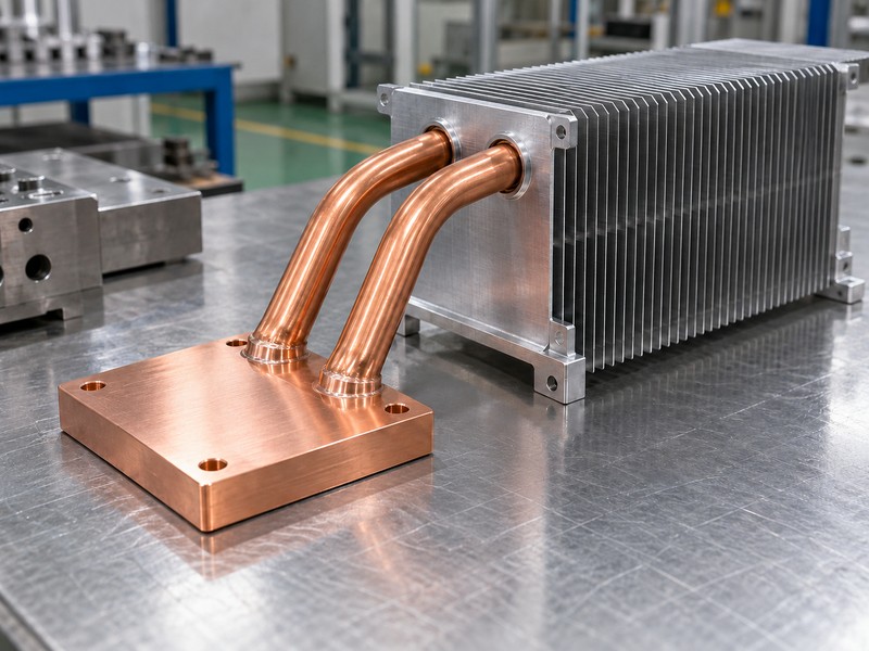
Copper helps spread concentrated heat into the tube contact region, especially when the device footprint is smaller than the cooling structure. In a copper tube heat sink, the base, tube wall and joints each contribute resistance. A higher conductivity metal helps only where solid conduction limits performance; it cannot lower inlet air temperature or restore missing airflow.
Specify grade and condition together
Material selection also affects forming, joining and dimensional control. State the copper grade, temper and applicable material specification rather than asking for “pure copper.” Review the supplier’s material data at the operating temperature, then assess the whole assembly. Replacing a well coupled copper base with a more expensive grade may offer less benefit than fixing a thick interface layer or an incomplete tube joint.
- Match tube temper to the approved forming process.
- Keep alloy identification tied to material records.
- Review surface condition before bonding or soldering.
| Design concern | Copper contribution | Separate constraint |
|---|---|---|
| Small source | Spreading into tube region | Contact area |
| Formed route | Ductile tube construction | Wick or wall damage |
| Added mass | Conductive structure | Mechanical support |
Choose the material after locating the dominant temperature drop in the proposed assembly.
3. How should you size the tube contact footprint?
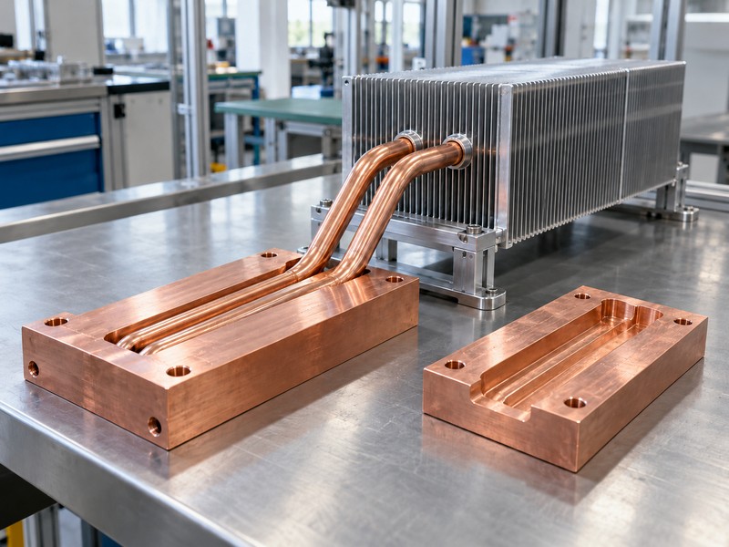
Size the contact footprint around the loaded area and the path heat must travel through the base. A copper tube heat sink needs enough bonded evaporator or coolant-tube contact to collect heat without leaving a long lateral conduction path. Tube diameter alone says little about how well a small device couples into that route.
Draw the source over the tube layout
Overlay the device footprint on a sectioned CAD view. Check the remaining base thickness, groove depth and distance between the source edge and each tube. For a hypothetical screening example, assume a uniformly heated square device and compare centered and offset positions at identical power. The offset arrangement changes spreading distance even though both assemblies contain exactly the same copper mass.
- Mark actual dissipating regions rather than package outlines alone.
- Keep mounting holes clear of tube walls.
- Define contact lengths separately from total tube length.
| Drawing feature | What it controls |
|---|---|
| Source position | Local spreading distance |
| Groove depth | Base conduction and tube protection |
| Bonded length | Usable heat pickup area |
Request a thermal review whenever a device moves relative to the approved tube route.
4. Which tube-to-base joint should you specify?
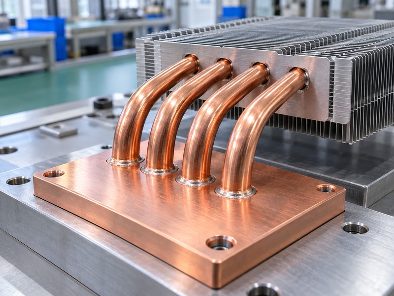
Specify a joint that provides repeatable thermal contact while preserving the tube and surrounding assembly. A copper tube heat sink may use a controlled mechanical fit, soldered connection or qualified adhesive system. The choice depends on materials, geometry, process temperature and service conditions. No joining label guarantees low resistance without an adequately filled, stable contact region.
Make joint quality observable
Put joint coverage, acceptable gaps and inspection methods into the manufacturing discussion. A joint can look continuous at its edges while containing internal voids. For sealed heat pipes, the assembly process must remain within the pipe manufacturer’s permitted thermal and mechanical limits. Evaluate adhesive bond thickness, cure conditions and temperature exposure instead of selecting adhesive from its conductivity value alone.
- Define surface preparation and cleanliness requirements.
- Protect sealed tubes from unapproved heating or machining.
- Correlate inspection evidence with assembly thermal checks.
| Joining route | Detail to control |
|---|---|
| Mechanical fit | Contact pressure and retention |
| Soldered joint | Coverage and process temperature |
| Adhesive bond | Thickness, cure and voids |
Approve the finished joint process along with the tube specification, because both determine the heat path.
5. How do copper tubes connect with useful fin area?
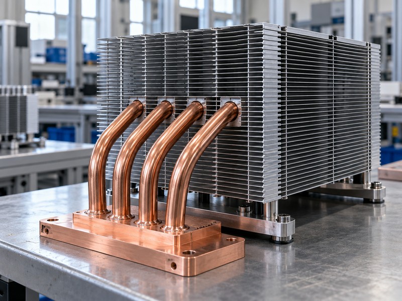
Connect the condenser region across fins that receive useful airflow, with controlled contact between every intended tube and fin. A copper tube heat sink often combines copper heat transport with lighter aluminum fins. The resulting performance depends on tube distribution, fin contact and channel flow; adding fin area can disappoint when most air bypasses the stack.
Review the fin stack with the fan and duct
A zipper fin assembly offers repeated channels and configurable pipe locations, but its pitch still needs to match available fan pressure. Check inlet obstructions, outlet clearance and enclosure recirculation in the installed model. A warm fin region beside a cooler region may indicate uneven heat delivery, uneven airflow or both, so investigate those paths separately.
- Identify the condenser length actually coupled to fins.
- Control collars or other pipe-to-fin contact features.
- Include bypass gaps when evaluating installed airflow.
| Observation | Possible check |
|---|---|
| Hot base, cool fins | Tube and joint coupling |
| Hot fins, hot base | Air-side rejection |
| Uneven fin temperatures | Heat distribution and airflow |
Match the tube layout to the air that can pass through the finished enclosure.
6. What changes when you bend or flatten the tubes?
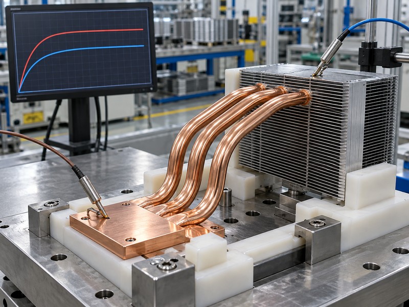
Bending and flattening change the tube’s internal geometry and can reduce its usable transport capacity. For a sealed copper tube heat sink, deformation can restrict the vapor space or damage liquid return paths. For a pumped tube, it can alter flow area and wall condition. Approve the finished shape rather than relying on data for a straight tube.
Give the supplier a controlled forming envelope
State bend locations, centerline radii, flattened lengths and final dimensions on the drawing. Limits depend on tube construction and tooling, so avoid applying a universal radius multiplier. Keep tube crossings and closely spaced bends visible in the design review. A route that clears every component in CAD may still leave insufficient tooling access or a weak unsupported span after assembly.
- Define datums for measuring the formed route.
- Request thermal evaluation after all forming operations.
- Add support where handling loads could reach the tube.
| Feature | Sealed heat pipe concern | Pumped tube concern |
|---|---|---|
| Bend | Wick and vapor space | Ovality and wall thinning |
| Flattening | Return and transport limits | Flow restriction |
| Long span | Joint loading | Joint loading |
Release geometry and test evidence as one configuration whenever packaging forces a new tube shape.
7. How do mounting and interfaces affect the result?
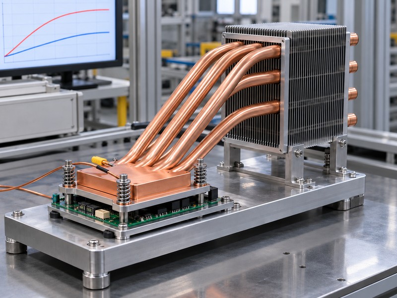
Mounting establishes the contact pressure and alignment through which heat enters the assembly. A copper tube heat sink with excellent internal transport can still run hot if its base rocks on the package or the interface remains too thick. Use device load limits and the real tolerance stack when defining the installed joint.
Control force without loading the tubes
Review heat sink mounting hardware with the base and interface material. Fasteners should seat the contact face through a supported load path rather than pull on remote tubing or thin fins. Include electrical isolation where the equipment requires it. Measure surface flatness and assembled contact using the same datums that locate the heat source.
- State the interface material and installed thickness.
- Define spring deflection or another controlled force method.
- Check board support and permitted package loading.
| Interface variable | Consequence of poor control |
|---|---|
| Flatness | Partial contact |
| Clamping force | Excess resistance or device stress |
| Assembly gap | Uncontrolled interface thickness |
Approve the mounting stack before attributing a high device temperature to the tubes.
8. When is a pumped copper tube cold plate preferable?
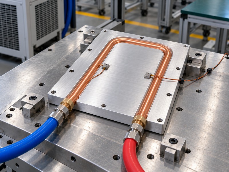
A pumped circuit becomes attractive when local airflow cannot reject the required heat and a suitable liquid loop already exists. The copper tube heat sink selection then extends beyond the plate to coolant temperature, flow, pressure and loop compatibility. A tube-in-plate cold plate transfers heat into flowing coolant through a continuous thermal path.
Evaluate the whole wetted circuit
Identify every wetted metal, seal and fitting, including the remote heat exchanger. Coolant compatibility depends on the full circuit, fluid chemistry and maintenance plan. A copper tube embedded in an aluminum plate may keep the aluminum outside the wetted path, but that does not establish compatibility with an unrelated aluminum component elsewhere in the loop. Record allowable pressure drop alongside thermal requirements.
- Specify coolant composition and inlet temperature range.
- Define flow at the plate rather than pump nameplate flow.
- Agree leak and pressure acceptance conditions.
| Requirement | Needed definition |
|---|---|
| Thermal boundary | Coolant inlet temperature and flow |
| Hydraulic boundary | Pressure and pressure drop |
| Durability | Wetted materials and fluid control |
Select pumped cooling only after the loop owner accepts its operating and maintenance requirements.
9. How should you compare assembly test reports?
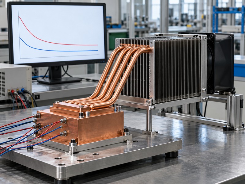
Compare reports at matched heat input, mounting, orientation and rejection conditions. A copper tube heat sink temperature has little meaning without its reference temperature and sensor position. A base measurement describes the assembly contact region; junction temperature also includes the device’s internal thermal path. State which temperature governs the equipment acceptance decision.
Separate resistance from transport capacity
Under a defined steady condition, thermal resistance equals temperature rise divided by heat input. A hypothetical base at 70°C with 30°C inlet air and 200 W effective heat input gives 0.20 K/W. Those assumed values illustrate the calculation, not a product rating. The result does not establish how much additional power a heat pipe can carry before its operating limit is reached.
- Record effective heat input and fixture heat losses.
- Measure inlet air near the actual fin entrance.
- Test the approved mounting and worst permitted attitude.
| Report item | Why it is needed |
|---|---|
| Sensor map | Defines measured temperature |
| Installed flow | Defines air or liquid boundary |
| Power sweep | Reveals response beyond one point |
Use matched conditions to identify whether a proposed change improves your equipment’s limiting temperature.
10. What should your copper tube heat sink RFQ include?
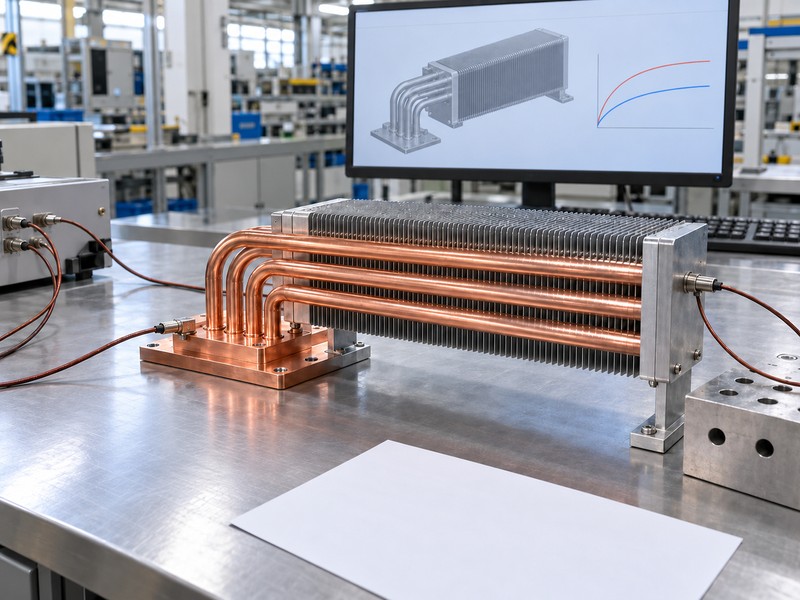
An RFQ should connect thermal conditions, mechanical geometry and acceptance evidence in one revision package. A copper tube heat sink quotation becomes easier to compare when every supplier receives the same source map, allowable temperature and installation attitudes. Separate required dimensions from dimensions that suppliers may adjust, then ask them to identify assumptions before making samples.
Prepare a package that engineering can evaluate
- Supply CAD, source footprints and component load limits.
- State airflow or coolant conditions across the operating range.
- Define sample acceptance, inspection records and expected quantities.
| RFQ input | Decision it supports |
|---|---|
| Power and temperature limits | Thermal target |
| Envelope and mounting | Assembly feasibility |
| Test and inspection plan | Sample approval |
Resolve missing boundary conditions before comparing piece prices from competing assembly concepts.
FAQ
Q1. Can I identify a heat pipe from copper color?
No. Confirm sealed construction and internal specification; external color cannot identify the transport mechanism.
Q2. Can I drill the base after receiving it?
Only with an approved machining drawing. Embedded tube locations and wall clearance must be protected.
Q3. What is the best copper grade for every design?
There is no universal grade. Conductivity, forming, joining and material compatibility require a coordinated choice.
Q4. How do I know if more tubes will help?
Locate the dominant resistance. Extra tubes may help transport while leaving airflow or interface limits unresolved.
Q5. Can I approve the assembly from a single temperature?
No. Record its power, reference temperature, flow, mounting and orientation so the result can be reproduced.
For an engineering review, send Morton your source map, installation drawing and operating conditions and identify the sample tests your team will use for approval.