
Match a heat pipe heat sink to the specified heat load, source footprint, available fin area and installed airflow. It lets a compact heat source use a larger or offset fin area. When a processor sits behind a connector bank or below a crowded cover, the practical task is to connect it with useful airflow while keeping every thermal interface under control.
1. What parts form a complete heat pipe heat sink?
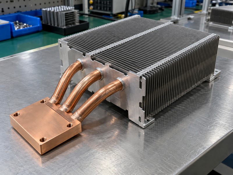
A complete heat pipe heat sink has a source contact region, one or more sealed heat pipes, a condenser connection and a heat rejection surface. The base collects heat from the device, pipes carry it across the available route and fins transfer it into air. Each connection needs enough contact area and a stable mechanical assembly to perform its assigned role.
Follow the path from package to air
Draw the thermal path beside the mechanical layout. That exercise separates a source contact problem from a transport problem or an air-side problem. A base can remain too hot even when the pipes work correctly if the fins receive already heated air. Conversely, cool remote fins alongside a hot base justify checking the joints and the path into the evaporators before changing the fan.
- Identify the actual device contact footprint.
- Mark evaporator and condenser attachment regions.
- Locate the air inlet and enclosure exhaust.
| Assembly part | Thermal role |
|---|---|
| Contact base | Collect and spread heat |
| Sealed pipe | Transport between regions |
| Fin stack | Release heat into air |
Specify the complete source-to-air path whenever evaluating an assembly drawing or supplier proposal.
2. How does evaporation move heat inside the pipe?
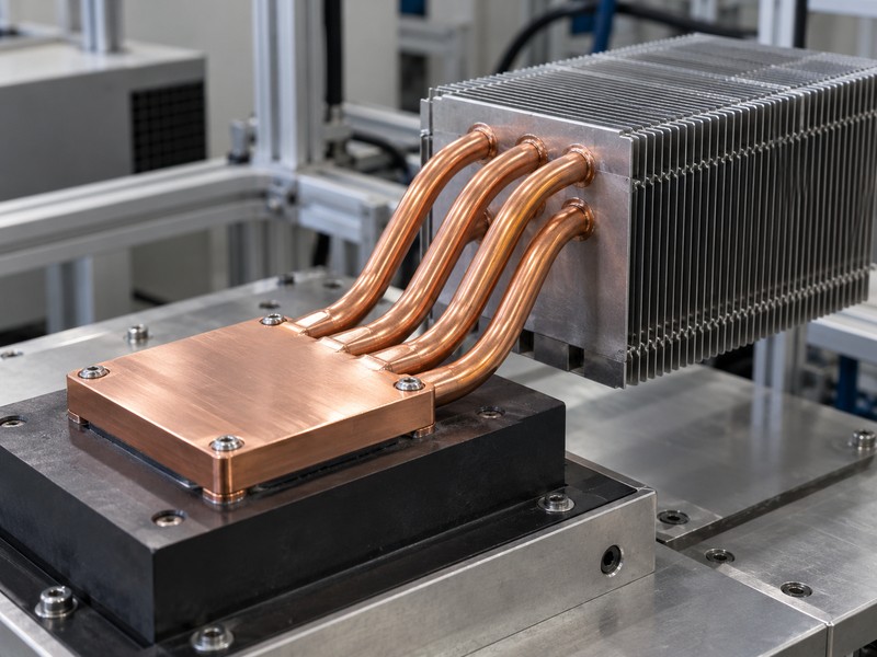
Evaporation absorbs energy from liquid at the heated region, allowing vapor to carry energy toward a cooler region. In a heat pipe heat sink, the working fluid and internal pressure are selected for the intended operating range. Water inside an appropriately evacuated copper heat pipe can evaporate at electronics cooling temperatures; atmospheric boiling temperature does not describe that sealed operating condition.
Keep the heated region connected to liquid
The source transfers heat through the external joint, copper wall and internal wick region before evaporation occurs. Concentrating the same power into a smaller effective footprint can stress this pickup region even when total power stays unchanged. A heat source map helps identify that local demand. Treat an exposed pipe touching only a narrow line on a package as an interface geometry requiring engineering review.
- Define the heated length and effective contact area.
- Check local heat input beside total assembly power.
- Evaluate the specified fluid within its operating window.
| Region | What happens |
|---|---|
| External contact | Heat crosses the joint |
| Evaporator wall and wick | Liquid receives energy |
| Vapor space | Vapor carries energy onward |
Give the supplier source dimensions so it can evaluate heat pickup and transport capacity.
3. How do condensation and liquid return complete the cycle?
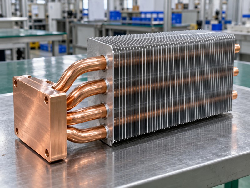
Condensation releases energy into the cooler condenser, while capillary action in a suitable wick returns liquid toward the evaporator. A heat pipe heat sink repeats this cycle without an external liquid pump. It still requires a cooler rejection boundary, because the internal cycle cannot remove heat from an assembly that has nowhere to release it.
Match the condenser with a usable rejection surface
The condenser may connect to a remote fin pack, a larger spreader or another cooled structure. Its usable contact length is the region that actually transfers heat into that structure, rather than every pipe segment beyond the source. Wick selection and gravity affect liquid return. In an adverse attitude, the wick must return liquid uphill while also overcoming internal flow losses.
- Show the complete condenser contact region on the drawing.
- State all permitted installation attitudes.
- Keep unsupported pipe length out of assumed rejection area.
| Process | Required condition |
|---|---|
| Condensation | Cooler, coupled rejection region |
| Liquid return | Adequate wick pumping capability |
| Continuous operation | Heat input within operating limits |
Confirm both thermal attachment regions and the installed attitude before accepting a transport estimate.
4. What temperature drop should you expect?
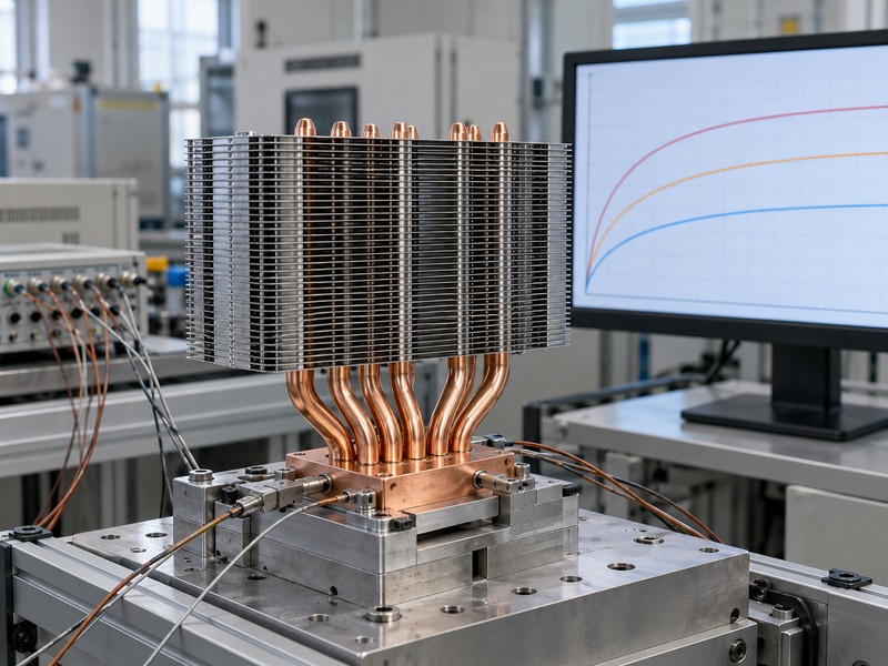
Expect a temperature drop across every part of the thermal path, with its size determined by geometry and operating conditions. A heat pipe heat sink has finite resistance through its interfaces, transport region and fins. Claims about very high effective conductivity describe a particular measurement convention; they do not establish the device temperature of a complete industrial assembly.
Build a resistance budget with clear reference points
For a hypothetical steady-state screening case, assume 100 W dissipates through a base-to-inlet-air resistance of 0.30 K/W. The predicted base rise is 30 K, before adding interface and device-internal temperature rises. This arithmetic assumes that resistance applies at the stated airflow, attitude and mounting condition. Actual assemblies may respond nonlinearly as airflow, temperature or transport behavior changes, so use the estimate to plan measurements.
- Define whether the limit applies to junction, case or base.
- Separate the interface contribution from the air-side contribution.
- Reserve project-specific margin for uncertainty and variation.
| Quantity | Defined relationship |
|---|---|
| Temperature rise | Measured point minus reference |
| Thermal resistance | Temperature rise divided by power |
| Device temperature | Includes its internal heat path |
Choose sensor locations and temperature limits before comparing thermal resistance values from different reports.
5. Why place the fins away from the heat source?
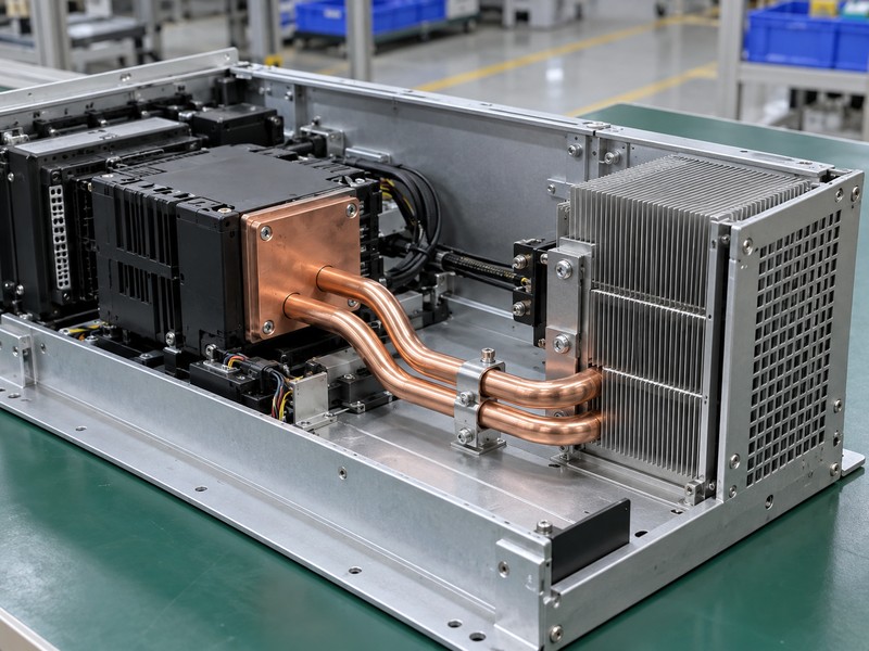
Remote fins can reach a larger, less obstructed airflow channel than the space immediately above the device. A heat pipe heat sink uses transport length to connect those locations within its operating limits. This can free the source region for connectors or shielding, but the route must preserve installation access, mechanical support and adequate condenser contact.
Put the fin stack where air can do useful work
Review the fin footprint together with the enclosure airflow path. A zipper fin heat sink can place repeated fin channels around formed pipes, with pitch and dimensions selected for the available flow. Keep the outlet clear and avoid exhausting into a pocket that feeds warmed air back to the inlet. Include duct leakage when estimating how much fan flow enters the stack.
- Mark connector and cable keep-outs in the assembly model.
- Define the unobstructed inlet and outlet space.
- Support the fin mass through deliberate mounting points.
| Packaging issue | Layout response |
|---|---|
| Crowded source | Route toward an open channel |
| Air bypass | Add controlled duct boundaries |
| Heavy remote fins | Provide structural support |
Use remote fins when their air access compensates for the added route and assembly interfaces.
6. Should you use natural convection or a fan?
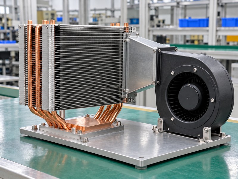
Use natural convection when the enclosure can reject the required heat with the permitted temperature rise and installation orientation. Use a fan when an evaluated forced-air path provides the needed rejection. A heat pipe heat sink transports heat passively inside its sealed pipes even when a powered fan moves air across its fins.
Match fin spacing to the installed flow mechanism
Natural convection relies on buoyancy and open flow paths, so closely packed channels can obstruct the available motion. Forced convection allows different fin arrangements, but denser fins raise flow resistance. Select the fan from its pressure-flow behavior in the installed system rather than its unrestricted airflow rating. Filters, guards, duct bends and neighboring equipment all contribute to the operating point.
- Check equipment attitude for buoyancy-driven airflow.
- Evaluate filter loading and inlet restrictions.
- Define fan failure behavior where temperature protection requires it.
| Cooling approach | Boundary to verify |
|---|---|
| Natural convection | Orientation and open air path |
| Forced convection | Installed flow and pressure drop |
| Shared system fan | Competing branches and recirculation |
Select the air-side architecture before freezing fin density or using catalog sink-to-air values.
7. What limits heat pipe heat sink operation?
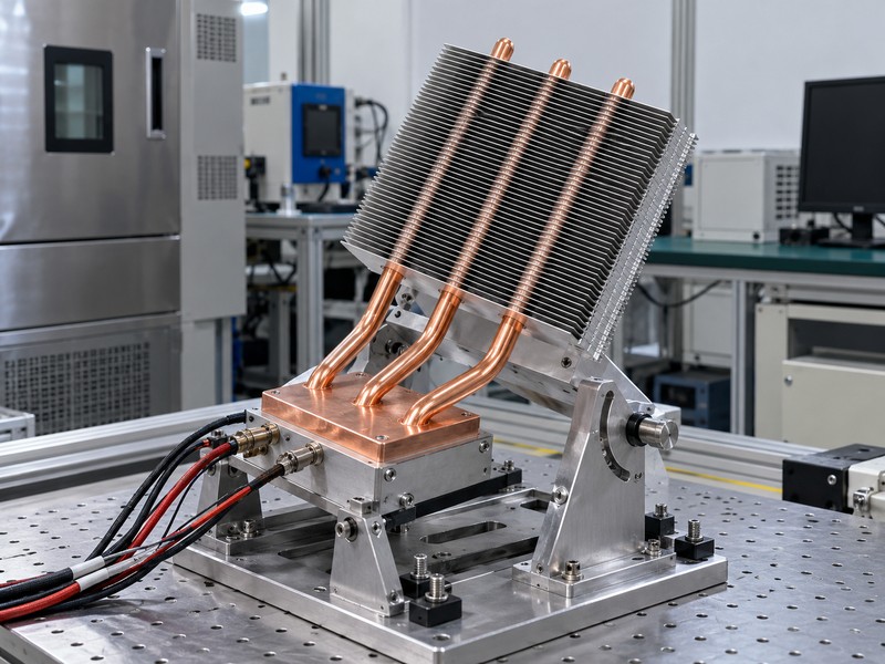
Operation is limited by the pipe’s ability to sustain vapor transport, liquid return and heat pickup under the actual conditions. A heat pipe heat sink needs more than a nominal wattage label. Temperature, wick, length, diameter, formed geometry and orientation can change the available transport capacity, sometimes before the fins reach their rejection limit.
Qualify the difficult operating conditions
In many terrestrial designs, insufficient capillary return can dry part of the evaporator as power rises. Other limits involve vapor flow, entrainment or excessive heat flux into the wick. Cold startup can differ from warm steady operation, and a water-filled design exposed below freezing needs an agreed freeze/thaw and startup evaluation. Survival through storage and performance immediately after power-on are separate acceptance questions.
- Test the most adverse approved source elevation.
- Include cold startup where the equipment requires it.
- Evaluate power transients rather than average power alone.
| Condition | Question to resolve |
|---|---|
| Adverse gravity | Can enough liquid return? |
| Cold startup | Does temperature remain acceptable? |
| Concentrated input | Can the evaporator collect the load? |
Request configuration-specific evidence instead of carrying a straight-pipe rating into a formed assembly.
8. How should the assembly attach to the device?
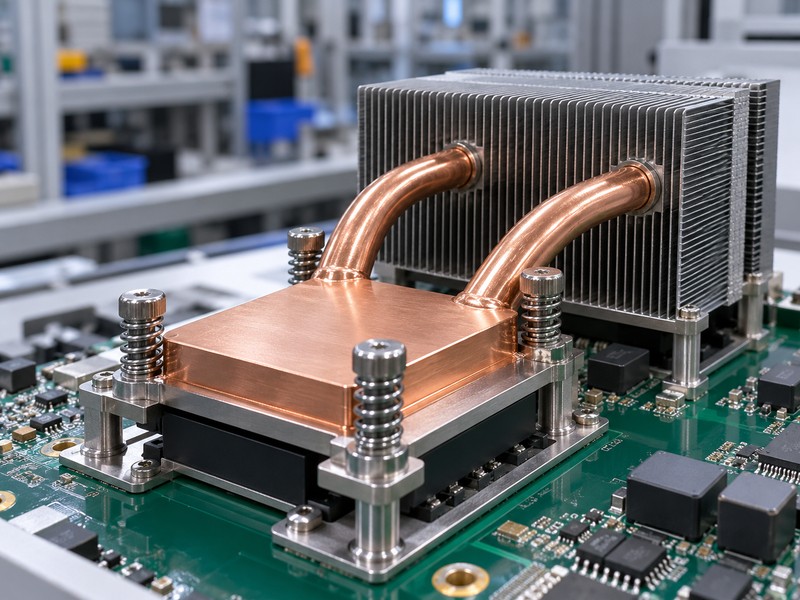
Attach the assembly through a flat contact surface, a defined interface material and a controlled load path. A heat pipe heat sink should transfer mounting force through its base and support features without bending the board or loading thin tube spans. Device mounting instructions establish the allowable forces and electrical boundaries for that joint.
Review contact and retention together
Coordinate mounting hardware with package height, board support and interface compression. Torque by itself does not define contact pressure across an arbitrary assembly. Spring travel, stops, fastener friction and surface seating can all affect the result. Where service removal is expected, specify the replacement or reuse policy for interface material and retaining parts before the assembly enters production.
- Inspect contact face flatness against agreed datums.
- Control the assembled gap and interface thickness.
- Support remote fin mass during vibration and handling.
| Mounting detail | What it protects |
|---|---|
| Defined force | Thermal contact and device load |
| Board support | Package and PCB strain |
| Independent fin support | Pipes and thermal joints |
Validate temperature and mechanical seating after the complete assembly reaches its installed condition.
9. When should you consider a pumped cold plate?
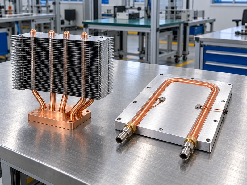
Consider a pumped cold plate when the local air path cannot meet the temperature requirement and an acceptable liquid rejection system is available. A heat pipe heat sink remains tied to its condenser temperature and air-side performance. A liquid plate creates a different boundary around coolant inlet temperature and flow, accompanied by hydraulic, leak-control and fluid-maintenance requirements.
Compare systems at their real boundaries
A tube-in-plate cold plate moves heat into a pumped circuit through tubing embedded in a plate. Include the remote heat exchanger, pump and controls in the comparison. If both concepts reject heat into the same warm room, liquid transport alone does not create a colder final environment. It can relocate rejection and improve local pickup while the complete system still needs adequate capacity.
- Define who supplies and controls the liquid loop.
- Check coolant chemistry against every wetted material.
- Compare service access, failure response and total system power.
| Decision factor | Air-cooled assembly | Pumped plate |
|---|---|---|
| Local dependency | Available airflow | Coolant boundary |
| Service concern | Fan and fouling | Fluid and connections |
| Integration | Duct and mounting | Loop and plumbing |
Choose liquid cooling when its complete operating boundary fits the equipment and ownership model.
10. How do you specify and approve the assembly?
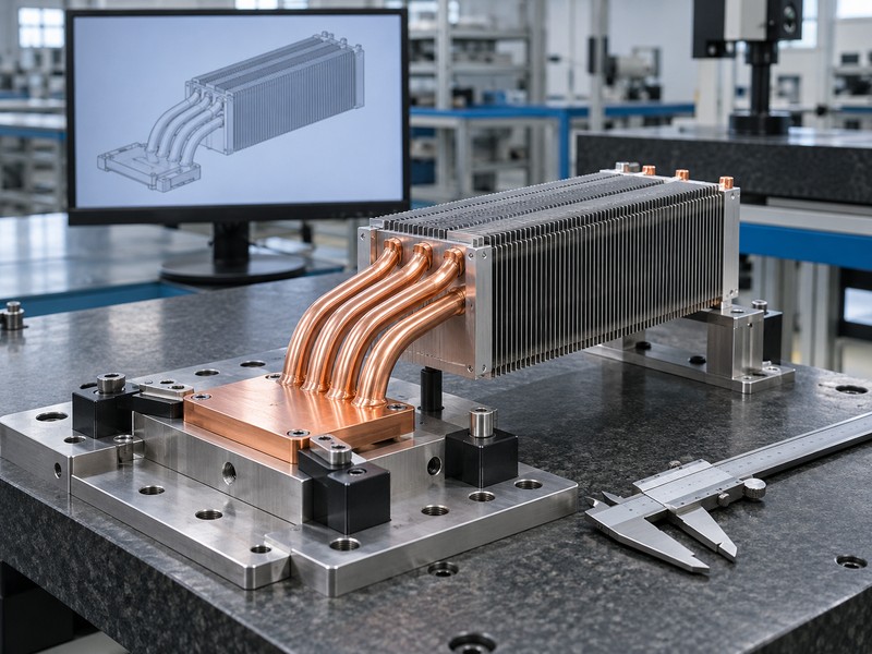
Approve a heat pipe heat sink against measured operating conditions and a released mechanical configuration. Send the supplier the source map, temperature limit, envelope, airflow and installation attitudes before requesting a sample. Agree sensor locations and steady-state criteria so your team can distinguish an assembly improvement from a change in fixture, mounting or inlet conditions.
Connect sample evidence with the production drawing
- Record the formed pipe geometry and approved joint process.
- Define critical dimensions and mounting requirements.
- Tie thermal acceptance and inspection records to a revision.
| Approval evidence | What it establishes |
|---|---|
| Thermal report | Performance at stated boundaries |
| Dimensional record | Fit and interface conformity |
| Controlled drawing | Repeatable build definition |
Release production only after the sample meets the agreed thermal and mechanical requirements.
FAQ
Q1. Can I run the pipes without a fan?
Yes, if the complete rejection surface meets the target through natural convection and radiation at the required attitude.
Q2. Does the working fluid need refilling?
No. A standard heat pipe is sealed; leakage or damage requires evaluation rather than routine refilling.
Q3. Can I bend an approved pipe afterward?
Only within an approved forming process. A changed route can alter capacity and invalidate previous test evidence.
Q4. How do I know if the fan is undersized?
Measure the installed flow and inlet temperature, then compare them with the assembly’s validated test conditions.
Q5. Can a heat pipe cool below its surroundings?
It cannot provide refrigeration by itself. Heat rejection requires a suitable cooler boundary.
Contact Morton with your source layout, airflow and permitted installation attitudes to define an assembly concept and the evidence needed for your sample review.