
Select a heat pipe design that meets the temperature budget across the equipment’s power map and installed orientations. Selecting a pipe diameter comes later. If your team begins with an empty CAD route and a total wattage, it can miss local heat flux, adverse gravity and interface losses. Build the operating specification and thermal budget before committing to the assembly shape.
1. What operating inputs should start heat pipe design?
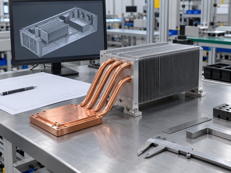
Start heat pipe design with a source map, temperature limits and rejection conditions for each relevant operating state. Total power describes only part of the load. Device location, active footprint, duty cycle and simultaneous operation determine where heat enters the assembly, while inlet air or coolant temperature determines the boundary available for rejection.
Define states that could set the temperature limit
Capture continuous operation, startup, overload and permitted equipment attitudes separately. Identify whether the controlling limit applies to a semiconductor junction, package case or mounting base, then supply the device thermal information needed to connect those locations. A brief that combines a peak power with an unrelated favorable ambient can produce a concept that meets neither actual operating state.
- Map individual sources and their active footprints.
- List simultaneous loads and transient durations.
- Define temperature references and measurement locations.
| Input | Engineering use |
|---|---|
| Source power map | Evaporator placement |
| Temperature boundary | Available thermal budget |
| Operating states | Qualification conditions |
Ask the equipment owner to approve these inputs before comparing candidate pipe layouts.
2. How do you allocate thermal resistance?
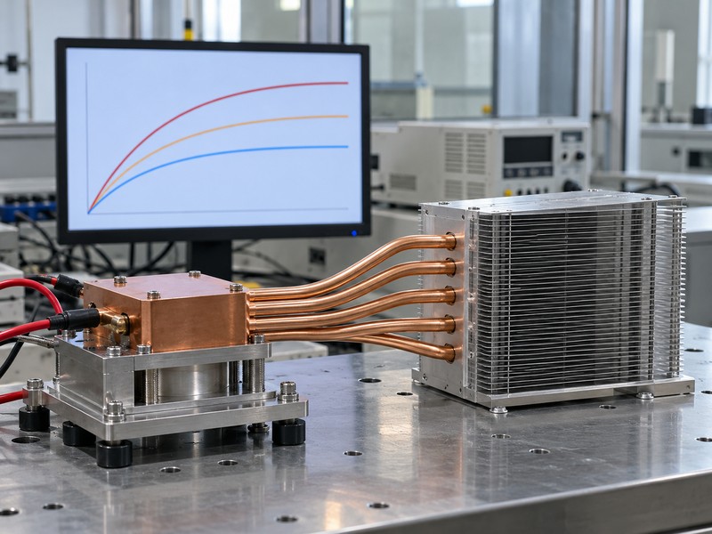
Allocate the allowable temperature rise across the device, interface, spreading region, heat transport and rejection surface. A heat pipe design must fit within that complete path rather than consume an assumed unlimited budget. At a defined steady operating point, the allowable total resistance is the permitted temperature rise divided by the relevant heat input.
Keep a screening calculation tied to assumptions
For a hypothetical example, assume a 120 W single source, a 90°C case limit and 40°C inlet air. The case-to-air budget is about 0.417 K/W. If the assumed interface contribution is 0.050 K/W, approximately 0.367 K/W remains for the assembly at that same condition. These assumed values illustrate allocation only; they provide neither a component rating nor a model for a distributed multi-source system.
- State which resistances are measured and which are estimated.
- Reserve an explicit project margin for uncertainty.
- Recalculate when source or inlet conditions change.
| Budget element | Information required |
|---|---|
| Interface | Contact area, thickness and load |
| Transport | Route, joints and operating state |
| Rejection | Fin geometry and installed airflow |
Use the budget to decide which temperature drop requires more evidence before the next design release.
3. When is a heat pipe appropriate for the heat map?
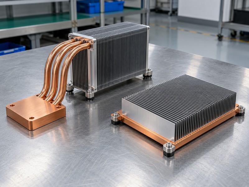
A pipe is appropriate when heat needs a defined route toward a larger or offset rejection region. A heat pipe design can connect a crowded source area with a fin stack near an air channel. A planar spreading layer may suit a different problem, where a concentrated source must distribute heat across a nearby broad fin base.
Compare geometries before selecting technologies
Review a vapor chamber heat sink when two-dimensional spreading fits the available envelope. Several pipes can also distribute heat across a base, but their contact pattern remains discrete and depends on the surrounding solid conduction path. Compare feasible assemblies using the same source map, height, mounting boundary and airflow. An isolated technology name cannot determine which concept will achieve the lower device temperature.
- Mark the distance between source and useful airflow.
- Check source coverage beneath each proposed transport region.
- Include support, joints and assembly access in the comparison.
| Thermal task | Candidate geometry |
|---|---|
| Offset fin stack | Routed heat pipes |
| Broad local spreading | Planar chamber or evaluated spreader |
| Short conductive path | Conventional solid base |
Select the geometry that addresses the measured or predicted bottleneck within the equipment envelope.
4. Which fluid and wick fit the operating range?
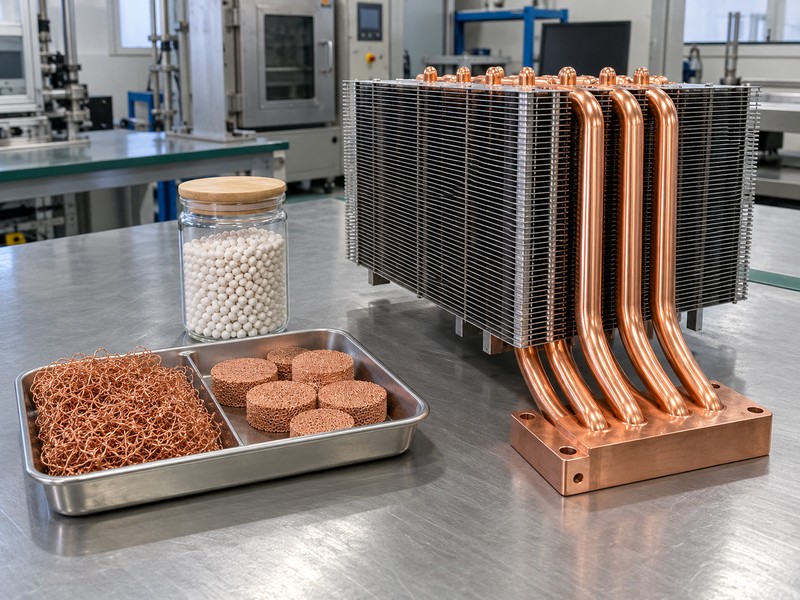
Choose a compatible envelope, working fluid and wick for the required temperature range and liquid-return demand. A heat pipe design depends on the properties of this combination rather than copper appearance alone. Copper-water construction is common in electronics cooling, while other temperature ranges and material compatibility requirements can require different fluid-envelope systems.
Treat wick selection as a hydraulic decision
A wick must generate enough capillary pressure to overcome liquid, vapor and gravity-related pressure demands. Finer pore structures can increase available capillary pressure, but liquid permeability also affects return losses. Sintered, mesh and grooved structures have different construction tradeoffs. Ask for performance evidence in the relevant orientation and geometry instead of assigning a universal ranking to the wick names.
- State operating and nonoperating temperature extremes.
- Identify adverse elevation and acceleration requirements.
- Ask how forming affects the selected internal structure.
| Selection item | Required check |
|---|---|
| Working fluid | Operating range and compatibility |
| Envelope | Pressure, joining and durability |
| Wick | Capillary return and flow losses |
Approve the internal construction against the intended operating envelope before relying on a capacity curve.
5. How do length and diameter affect transport?
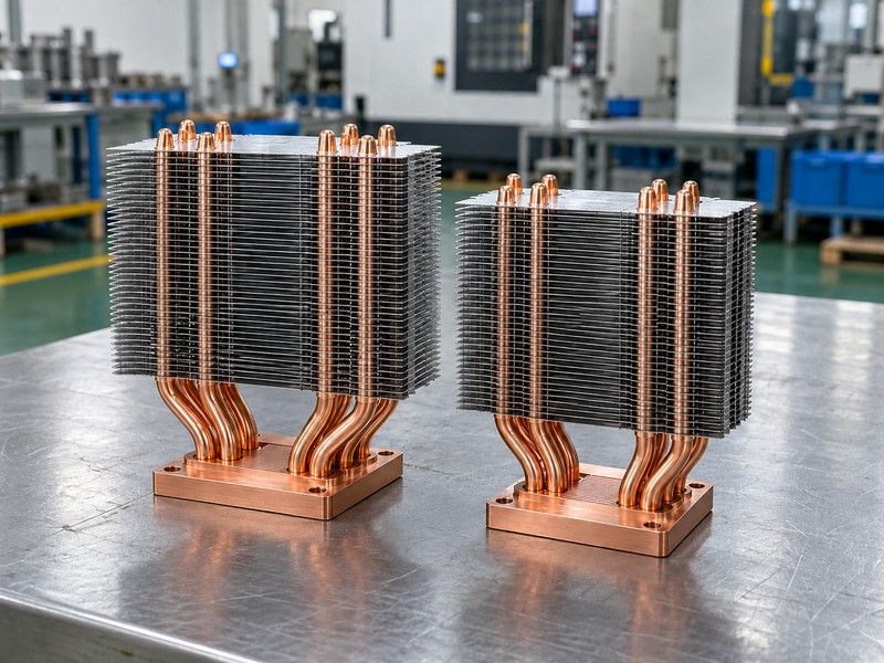
Length and diameter change vapor flow area, liquid-return losses and the space available for the wick. A heat pipe design needs the evaporator, condenser and intervening route defined separately. A longer pipe can reach better airflow, but the additional distance may reduce transport margin and adds mechanical packaging demands that a short catalog specimen does not represent.
Evaluate the useful sections of the route
Provide physical lengths and contact regions so the supplier can apply its stated effective-length convention. Increasing external diameter may increase internal transport space, but wall thickness and wick construction also consume that space. Multiple pipes can distribute collection and rejection across an assembly, yet their loads may differ because of source position and joint quality. Dividing total power equally is only an assumption until supported.
- Identify heated, unheated and cooled contact lengths.
- Check local loads on each pipe in a shared base.
- Keep total length distinct from the transport model’s length.
| Geometry item | Potential effect |
|---|---|
| Longer route | Higher internal flow losses |
| Larger diameter | More available internal area |
| Unequal source contact | Unequal pipe loading |
Compare candidate dimensions using the same temperature, attitude and contact definitions rather than diameter alone.
6. What must you check about orientation and startup?
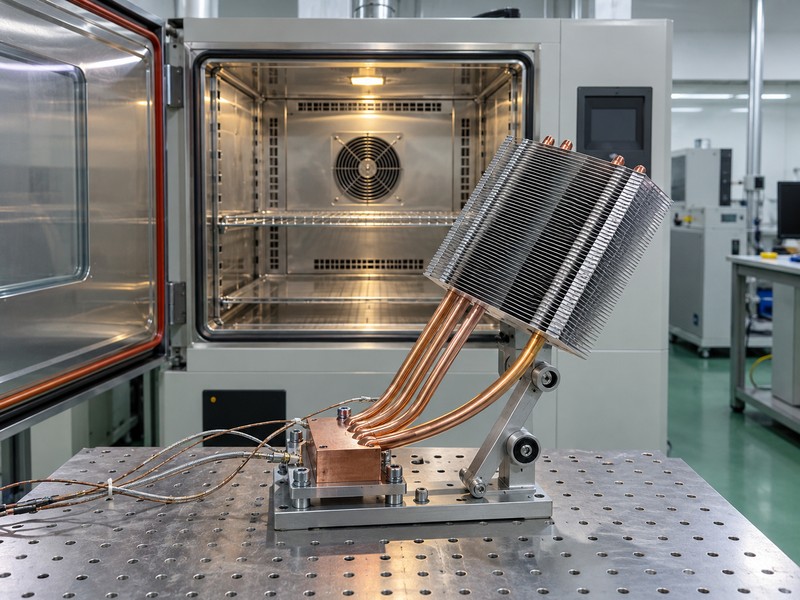
Check every permitted attitude and the startup conditions that could delay heat transport. A heat pipe design with its evaporator below the condenser can receive gravity assistance, while an elevated evaporator asks the wick to return liquid against gravity. A horizontal condition does not represent every wall, rack or mobile installation.
Qualify temperature transitions with the system load
At cold conditions, working-fluid properties and vapor density differ from warm operation. Water-filled pipes exposed below freezing need a qualified strategy for freeze/thaw survival and startup under load. Record the initial temperature, applied power profile and rejection boundary so the test can be reproduced. If the equipment changes attitude while running, add that motion and the related mechanical loading to the review.
- Define maximum adverse source elevation.
- Test startup at relevant initial temperatures.
- Include power control or protection behavior where required.
| Condition | Acceptance question |
|---|---|
| Adverse attitude | Is liquid return adequate? |
| Cold start | Does the device stay within its limit? |
| Thermal transition | Does transport recover predictably? |
Approve performance through the operating sequence and at the final steady temperature.
7. How should bends and flattening be controlled?
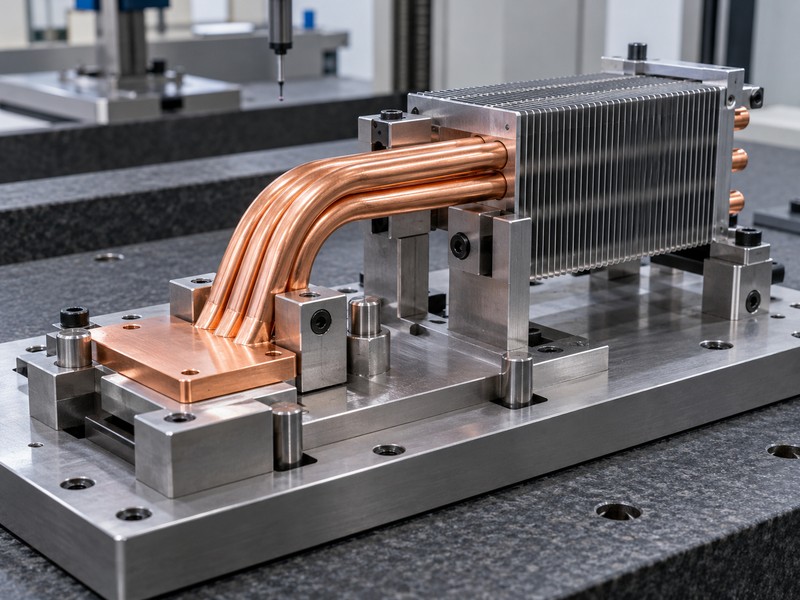
Control bends and flattening through supplier-approved geometry, tooling and inspection requirements. The heat pipe design changes when a bend restricts the vapor core, strains the wall or disrupts the wick. Flattening can improve external contact while reducing internal space, so the mechanical benefit needs to be checked against transport performance in the finished configuration.
Freeze the shape that will actually be tested
Provide centerline geometry, bend radii, flattened regions, datums and tolerances in the released model. Supplier-specific limits depend on pipe diameter, wall, wick and process. Avoid using a single radius rule as acceptance evidence for all constructions. Review assembly sequence too; a pipe that fits before the fin stack is installed may lack forming or joining access during the proposed production sequence.
- Keep sharp tool marks away from sealed tube walls.
- Check formed dimensions with an appropriate fixture.
- Repeat thermal evaluation after significant shape changes.
| Controlled feature | Inspection or verification |
|---|---|
| Bend profile | Radius and local deformation |
| Flattened region | Thickness and surface condition |
| Final route | Fit and configuration-specific test |
Treat a revised formed route as a design change requiring engineering review before substitution.
8. How do you design evaporator and condenser joints?
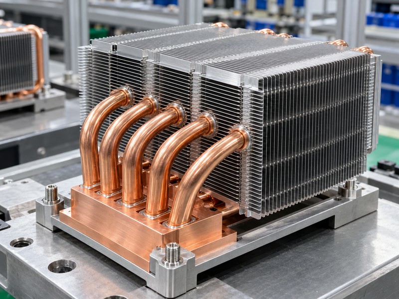
Design both joints around adequate contact area, controlled thickness and a process that preserves the sealed pipe. A heat pipe design includes these external connections because transport capacity has little value when heat cannot enter or leave effectively. Define the source-side base geometry and condenser-side fin attachment before assigning a resistance to the complete transport path.
Coordinate thermal joints with mechanical loads
An integrated zipper fin assembly needs controlled pipe-to-fin contact, while the base joint needs repeatable seating and attachment. Review mounting hardware so clamping and vibration loads travel through support features instead of stressing pipe joints. Joining temperature, adhesive cure or later machining must remain within the approved process limits. Include contact coverage and inspection access in the drawing review.
- Specify interface thickness and acceptable gaps.
- Protect tube walls from fasteners and cutting tools.
- Support remote mass without relying on thin pipe spans.
| Connection | Detail to control |
|---|---|
| Source to base | Flatness, interface and load |
| Base to pipe | Coverage and process condition |
| Pipe to fins | Contact and structural support |
Approve joint processes alongside the thermal model instead of treating them as unspecified assembly details.
9. How do you validate prototypes and model assumptions?
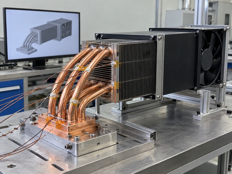
Validate prototypes by measuring the temperature path under controlled source, mounting and rejection conditions. Your heat pipe design model needs evidence for the formed assembly’s resistance and transport limits. A high equivalent conductivity entered into simulation may predict a smooth temperature field while hiding local pickup limits, joint resistance or adverse liquid-return conditions.
Test the assumptions that can change your decision
Use a defined source footprint, measured effective power and a sensor map covering the source interface and rejection region. Record installed airflow, inlet temperature and attitude, then compare the model at those same conditions. A power sweep can reveal a change in response that a single point misses. Investigate fixture heat leakage and sensor attachment before tuning model properties to match an unexplained result.
- Agree steady-state and transient acceptance criteria.
- Record repeat mounting behavior where it affects uncertainty.
- Separate model correlation from final equipment qualification.
| Evidence | Question answered |
|---|---|
| Temperature map | Where does the drop occur? |
| Power sweep | Is response stable across load? |
| Matched model | Are assumptions representative? |
Use test results to revise identified physical assumptions rather than merely adjusting a fitted conductivity value.
10. What should the released specification contain?
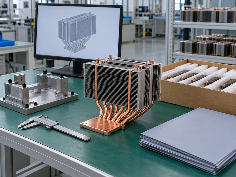
The released specification should connect the approved geometry, construction and operating conditions with measurable acceptance requirements. A heat pipe design is ready for production transfer when engineering and purchasing can identify which changes require review. A drawing that fixes the outside shape but leaves internal construction, joint process and thermal acceptance undefined permits substitutions with different behavior.
Link the approved sample to repeat production
- Freeze the drawing, material references and assembly revision.
- Define critical dimensions, thermal checks and inspection records.
- Require review of construction, process or supplier substitutions.
| Release item | Controlled outcome |
|---|---|
| Drawing and BOM | Approved assembly definition |
| Test specification | Comparable acceptance evidence |
| Change procedure | Reviewed substitutions |
Make the acceptance boundary explicit before approving repeat orders against the sample.
FAQ
Q1. Can I choose diameter from wattage alone?
No. Length, contacts, temperature, wick, geometry and orientation also determine available transport capacity.
Q2. What is the best wick for an uphill route?
Choose from verified performance at the required elevation and load. Wick names alone do not establish adequate return.
Q3. Can I reuse a straight-pipe simulation after forming?
Only if validated properties represent the formed geometry. Bends and flattening can change transport and resistance.
Q4. How do I know whether a prototype passed?
Compare measurements with predefined temperature and mechanical limits under the specified operating and test conditions.
Q5. Should the RFQ include startup requirements?
Yes. Startup temperature, power sequence and installation attitude can require different checks from warm steady operation.
Send Morton your power map, mechanical envelope and acceptance conditions to review a candidate route and define the prototype evidence your design release requires.