
Use a vapor chamber to spread heat across a local base, or heat pipes to connect the source with a remote cooling surface. Your vapor chamber vs heat pipe decision starts with where heat enters and where your equipment can reject it. A crowded industrial controller may have room above its processor but little usable airflow there. Comparing the complete thermal paths helps you choose a workable assembly before its enclosure and mounting points become fixed.
1. How do vapor chambers and heat pipes move heat?
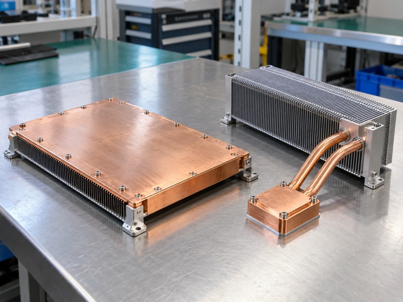
Both devices move heat through evaporation, vapor transport, condensation, and liquid return, so vapor chamber vs heat pipe selection begins with geometry. A conventional wicked heat pipe encloses the cycle within a tube. A conventional vapor chamber uses a broad sealed cavity with a wick and internal supports. Neither requires an external coolant pump, although its final heat exchanger may need a fan.
What stays the same inside each device?
Heat enters through the wall and evaporates working fluid near the source. Vapor reaches cooler surfaces and condenses, releasing heat into a base, fins, or another heat exchanger. The wick returns liquid toward the evaporator through capillary action; gravity can assist or oppose that return. Your source contact and condenser connection must both provide continuous thermal paths.
- Define evaporator and condenser contact areas.
- Identify the working fluid and container pairing.
- Keep the final heat rejection boundary explicit.
| Feature | Vapor chamber | Conventional heat pipe |
|---|---|---|
| Usual envelope | Broad sealed plate | Sealed tube |
| Main layout task | Spread across a plane | Connect selected regions |
| External pump | None | None |
Sketch the heat path through both devices and their heat exchanger before comparing individual component specifications.
2. When does a broad heat map favor a vapor chamber?
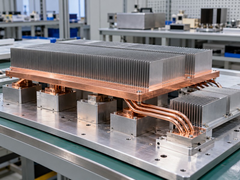
A broad, connected cooling base often favors a vapor chamber when spreading resistance dominates the temperature rise in a vapor chamber vs heat pipe comparison. A small source can heat only part of a large solid base effectively. A chamber can distribute energy across more of that base, provided its vapor space, wick, contact area, and condenser boundary suit the operating conditions.
How should you map several sources?
Plot each source footprint and its operating power separately. Include combinations in which one device runs hot while its neighbors idle, because the heat distribution changes with operating mode. A continuous chamber can couple nearby sources thermally, which may help sharing but can also warm a temperature-sensitive component. Evaluate each component’s allowable temperature rather than chasing uniformity alone.
- Show source positions on the contact drawing.
- Separate continuous load from short peaks.
- Mark components with tighter temperature limits.
| Heat-map feature | Question for the layout |
|---|---|
| Small central source | Can outer fins receive useful heat? |
| Several sources | Which load combination is limiting? |
| Sensitive neighbor | Will lateral heat spreading raise its temperature? |
Use the chamber’s spreading area where the assembly can reject that redistributed heat into air or another cooling boundary.
3. When do heat pipes suit a remote fin stack?
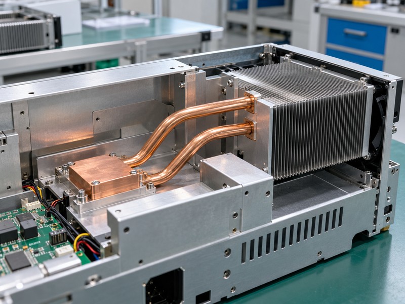
Heat pipes often suit a remote fin stack when heat must travel around obstructions or toward an available air channel in a vapor chamber vs heat pipe study. A tube can follow an approved formed route between contact blocks. Several pipes can serve separate source regions or distribute heat through a common stack, with their load sharing checked in the assembled design.
What makes a route practical?
Reserve space for bends, assembly fixtures, fasteners, and service access before freezing nearby hardware. Bending and flattening can change vapor passage area and damage a wick if the process exceeds the qualified geometry. Specify formed dimensions and tolerances with the supplier. Treat the pipe as a thermal component and support the assembly through designed brackets or structural parts.
- Keep the source block accessible for mounting.
- Preserve clearance around approved bend radii.
- Define how each condenser joins the fin stack.
| Routing constraint | Design response |
|---|---|
| Offset air channel | Route condensers toward that channel |
| Board obstruction | Review bend clearance in the full model |
| Shock or vibration | Support blocks and stack independently |
Choose a routed assembly only after its formed geometry and both thermal connections fit within the real enclosure.
4. How do thickness and mounting holes affect the choice?
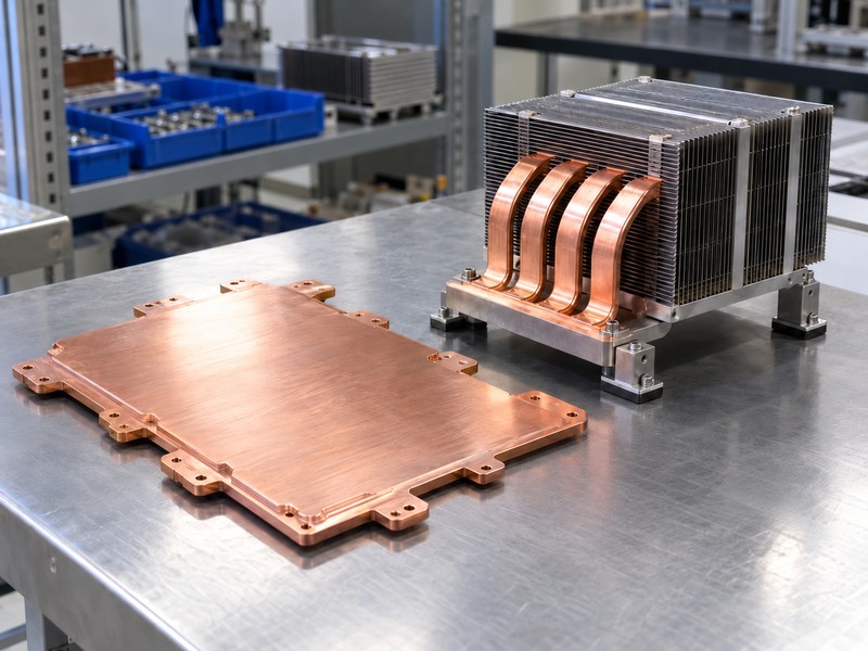
Thickness and mounting features can change the preferred vapor chamber vs heat pipe layout because the sealed internal spaces need room and mechanical support. A thin chamber may fit beneath a fin base, but thinning its vapor channel can restrict transport. Flattened pipes occupy a different footprint and may require a thicker supporting base. Compare the complete stack height, including the interface and fasteners.
Which features need early drawing review?
Through holes in a vapor chamber require designed sealed boundaries; drilling a finished chamber can destroy it. Internal supports also influence where clamping forces can enter the plate. Heat pipes embedded in a base need enough surrounding material for grooves, fastener threads, and contact-face machining. Leave electrical clearances and tool access visible in the same mechanical model.
- Mark mounting datums and prohibited machining zones.
- State maximum clamp force and package loading limits.
- Include flatness and contact-face requirements.
| Packaging feature | Check before release |
|---|---|
| Chamber through hole | Sealed feature approved in the original design |
| Flattened pipe | Remaining vapor space and formed-state performance |
| Mounting screw | Load path, engagement, and tool clearance |
Freeze the thermal envelope only after the mounting design preserves both internal flow space and a repeatable contact surface.
5. Does installation orientation change performance?
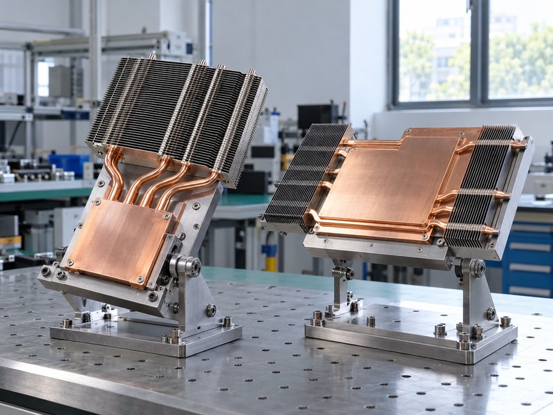
Installation orientation can change performance for both devices because liquid must return to the evaporator during a vapor chamber vs heat pipe evaluation. A wick provides capillary pumping, but its available pressure must overcome liquid and vapor flow losses plus any adverse elevation. A statement that a device contains a wick does not qualify every orientation or load condition.
Which positions should enter the test plan?
Define orientation using the actual evaporator and condenser elevations, rather than an ambiguous photograph marked vertical. For equipment installed in several positions, include each allowed arrangement and any tilt tolerance. Also separate normal operation from storage and transport conditions. A device that restarts after cold storage may need a different qualification sequence from an assembly that remains warm continuously.
- Identify the least favorable liquid-return direction.
- Test after the specified mounting and forming operations.
- Include startup at relevant ambient temperatures.
| Condition | Evidence to request |
|---|---|
| Gravity-assisted return | Thermal result in that installed position |
| Adverse elevation | Validated load and temperature margin |
| Changing orientation | Results across the permitted installation range |
Specify an orientation envelope in the purchase requirement and retain it with the accepted drawing and thermal report.
6. Can interfaces erase the spreading advantage?
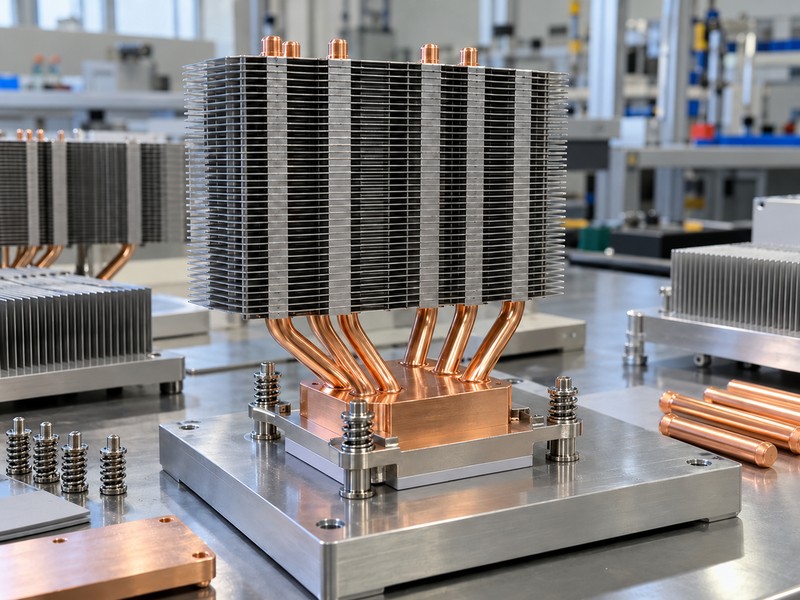
Interfaces can consume enough temperature margin to change a vapor chamber vs heat pipe decision, even when the internal two-phase path performs well. Heat must cross the device interface, contact base, joining layers, and condenser connection. Poor contact or an unsuitable bond can add resistance before the heat reaches useful fin area. Review heat sink mounting hardware with the contact stack rather than selecting it afterward.
Where should you place measurement boundaries?
Distinguish the package temperature, base temperature, evaporator wall temperature, and inlet air temperature. Those measurements include different parts of the thermal path. A lower pipe wall temperature difference cannot establish a lower package temperature unless the other resistances and cooling conditions are comparable. Record interface thickness and mounting force when testing either assembly.
- Define source contact flatness and surface finish.
- Control interface material, placement, and compressed thickness.
- Inspect the fin attachment and base connection.
| Interface | Possible consequence |
|---|---|
| Device to base | Local gaps raise source temperature |
| Pipe or chamber to fins | Poor bonding reduces usable fin area |
| Fastener stack | Uneven loading changes contact resistance |
Compare alternatives with equivalent contact conditions so the selected device receives credit only for performance it contributes.
7. How should you compare the thermal budgets?
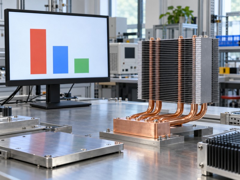
Compare source temperature at matched boundary conditions, then identify which resistance changes in the vapor chamber vs heat pipe study. Use a consistent source-to-cooling-medium boundary for the overall budget. Individual transport and spreading resistances can explain the result, but their measurement locations must agree with your model. Effective conductivity figures alone cannot settle a comparison between different shapes.
What does a hypothetical budget reveal?
Assume a hypothetical steady 100 W source, 35 °C inlet air, and a 75 °C allowable contact-base temperature. The allowable base-to-inlet-air resistance is then 0.40 K/W, before any separately budgeted package and interface rise. If an illustrative budget assigns 0.30 K/W to air-side rejection, only 0.10 K/W remains for other included losses. A better spreader cannot recover temperature margin consumed by inadequate installed airflow.
- Keep all temperature boundaries on the diagram.
- State whether interface resistance is included.
- Use the installed fan operating point for both options.
| Hypothetical budget item | Assumed value |
|---|---|
| Available base temperature rise | 40 K |
| Steady heat load | 100 W |
| Allowable base-to-air resistance | 0.40 K/W |
Spend prototype effort on the largest uncertain part of the budget before selecting a more complex spreading structure.
8. Which design has the lower production cost?
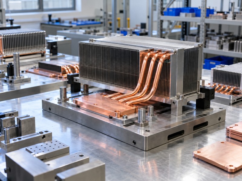
The lower production cost depends on the complete assembly and its acceptance requirements, so vapor chamber vs heat pipe pricing needs matched drawings and volumes. A simple formed pipe may cost less than a custom chamber, while several pipes, a machined base, and multiple joints can reverse that result. Tooling, joining yield, inspection access, and revision risk belong in the comparison.
What should purchasing compare beyond piece price?
Ask for the same source interface, fin envelope, orientation range, and validation scope in each quotation. Separate one-time engineering or tooling charges from recurring assembly cost. A cheaper component can require extra machining or a more difficult joining operation elsewhere. If one design depends on a tight tolerance, ask how production will measure that feature and control changes.
- Compare delivered assemblies with equivalent thermal targets.
- List tooling ownership and drawing revision terms.
- Define sample, inspection, and packaging requirements.
| Cost element | Clarification for quotation |
|---|---|
| Base and joints | Which operations enter the quoted assembly? |
| Verification | Which thermal and dimensional checks are included? |
| Production change | What requires review and requalification? |
Select the cost comparison boundary before requesting prices, so engineering and purchasing evaluate the same finished thermal path.
9. How do you test both options fairly?
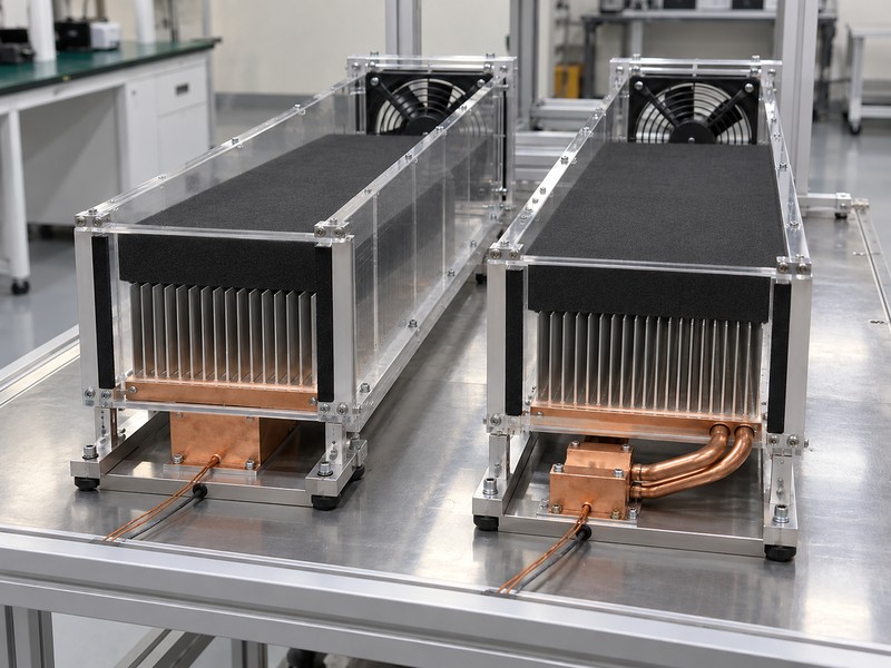
Test both assemblies with matched heat sources, contact conditions, and cooling boundaries to obtain a useful vapor chamber vs heat pipe comparison. The same fan command can produce different airflow through different fin stacks. Use installed airflow measurements or a controlled duct arrangement, then record pressure and temperature conditions. Inspect zipper fin heat sinks for bypass paths as part of that setup.
Which results should the report preserve?
Record local source temperatures, evaporator and condenser sensor positions, inlet temperature, load steps, and time histories. Use a stated stability criterion before accepting steady-state readings. Repeat a mounting cycle when interface variation could influence the decision. A qualitative curve can explain trends, but release decisions need measured data and a defined uncertainty assessment.
- Test the limiting source combination and orientation.
- Check startup and sustained operating behavior.
- Preserve raw readings alongside calculated resistance.
| Test control | Why it affects the comparison |
|---|---|
| Source footprint | Changes spreading demand |
| Installed airflow | Changes fin heat rejection |
| Sensor location | Changes the measured temperature difference |
Approve the assembly that meets the equipment temperature limits under the agreed test conditions with the required margin.
10. What does a vapor chamber vs heat pipe review need?
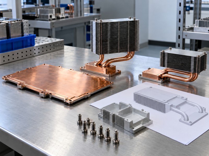
Send a heat map, mechanical envelope, cooling boundary, and acceptance target so a vapor chamber vs heat pipe review can compare buildable alternatives. Include conditions that might rule out a layout, such as restricted mounting access or adverse orientation. Morton can be approached with that brief without assuming a specific device has already qualified. Keep unresolved values visible instead of replacing them with convenient defaults.
What belongs in the RFQ package?
Provide the model revision and identify which dimensions are fixed. Your thermal brief should distinguish measured operating conditions from design estimates. State required sample quantities, annual demand, and target milestones so quotations share a commercial basis. Ask that proposed changes to the thermal path return for review before sample approval.
- Source footprints, powers, and allowable temperatures.
- Airflow or coolant conditions and installation orientation.
- Contact stack, mounting loads, and verification method.
| RFQ attachment | Required content |
|---|---|
| Mechanical model | Envelope, datums, clearances, mounting |
| Thermal brief | Heat map and cooling boundary |
| Acceptance plan | Temperature limits and test conditions |
Request an assembly proposal tied to those conditions so the next discussion can address specific tradeoffs.
FAQ
Q1. Can I replace several heat pipes with one chamber?
Possibly. Recheck source contact, fin attachment, mounting loads, and orientation before treating the designs as interchangeable.
Q2. What is the best choice for a remote air channel?
Heat pipes are often a practical candidate. Their approved routing can connect an obstructed source with a remote condenser stack.
Q3. How do I know if spreading resistance dominates?
Measure or model the base temperature distribution with defined source and cooling boundaries. Separate that gradient from interface and air-side losses.
Q4. Can either device work without a fan?
Yes, with a suitable passive heat exchanger. The complete assembly still needs enough natural convection or another heat rejection path.
Q5. Should I select a device using its maximum wattage?
Use a validated operating point. Capacity depends on geometry, temperature, orientation, contacts, and the condenser boundary.
For an equipment-specific review, send your drawing, heat map, installation orientation, and cooling conditions when you contact Morton.