
A DIY voltage regulator heat sink is a prototype cooling part made from controlled metal stock and attached through the regulator’s intended thermal surface. Use it to compare a design idea under measured conditions. Define the heat load, contact and insulation before cutting metal so the prototype answers a useful engineering question.
1. What should a DIY voltage regulator heat sink prove?
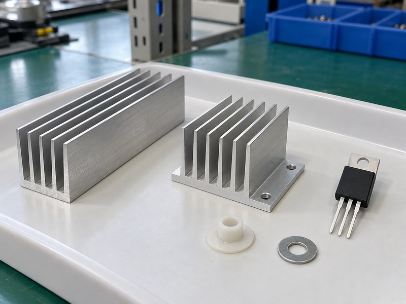
A DIY voltage regulator heat sink should prove whether a proposed contact, envelope or cooling arrangement deserves further development. It should not rely on an undocumented scrap shape that cannot be reproduced. Choose a question the prototype can answer, then keep its materials and test conditions traceable.
Set one design question
You might need to check whether a short extrusion fits a board, whether a chassis contact is practical or whether a new interface improves a mounting joint. Those questions require different samples and measurements. Define the decision before building several unrelated shapes, otherwise a temperature difference may be impossible to explain.
- State the load and local air condition.
- Identify the geometry or interface being compared.
- Define what result will justify another sample.
Keep the reference arrangement
Retain a baseline such as the original assembly or a suitable board-level heat sink. Compare it using the same regulator, mounting process and measurement method where practical. Document differences that cannot be held constant so the prototype report remains useful after the bench work ends.
| Prototype purpose | Evidence to collect |
|---|---|
| Mechanical fit | Envelope and contact inspection |
| Interface comparison | Controlled mounting and temperatures |
| Cooling concept | Loss, local ambient and steady behavior |
Build the sample around a decision you can make from its results.
2. How do you calculate the heat load before building?
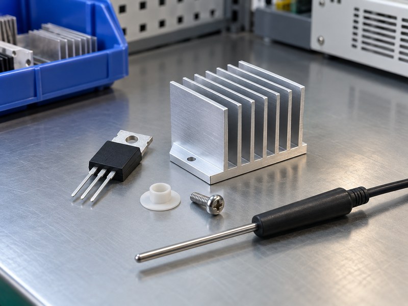
Calculate the DIY voltage regulator heat sink load from the selected device’s loss at a credible operating point. For a linear regulator, start with voltage drop multiplied by output current and include the applicable ground-current contribution. A switching converter needs its own component-loss model.
Use a declared example
An illustrative linear regulator reducing 10 V to 5 V at 0.4 A dissipates about 2 W before quiescent-current loss. That example describes the heat input, rather than a current rating for an unspecified package. Use the actual device’s voltage, current and thermal information when defining your prototype’s acceptance target.
- Measure input voltage at the device terminals.
- Record sustained output current and device loss.
- Check the highest credible operating loss.
Establish a temperature budget
Choose a junction target and local air temperature, then identify the applicable package and interface paths. A simple series model can screen a tab-mounted design, but a board-dominated package may need a different model. Keep the assumptions explicit instead of inferring a cooling requirement from package size.
| Input | Prototype record |
|---|---|
| Device loss | Calculation or suitable measurement |
| Local ambient | Air near the cooling surface |
| Junction target | Device-specific design limit |
The heat load and allowed rise tell you what the prototype must remove.
3. Which metal stock should you start with?
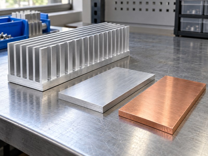
Start a DIY voltage regulator heat sink with identifiable stock that supports a repeatable contact surface and usable cooling geometry. A known extrusion offcut can be more informative than a random metal object. Material identity, thickness and finished condition should remain available in the prototype record.
Choose a reproducible starting shape
An existing fin profile provides open passages and a continuous base that can be compared with supplier data where suitable data exists. A flat plate can test a mounting concept, but its cooling behavior depends on area, orientation and surroundings. Extra mass may delay warming without providing the same steady-state heat rejection as added effective surface.
- Record material grade if known and required for the comparison.
- Inspect the stock for damage and uneven contact faces.
- Keep enough material to reproduce the sample.
Avoid unmeasured material assumptions
A plated or painted scrap part may hide a different base material or an insulating layer. Small decorative objects can also have poor contact geometry even when their material conducts heat. Use a known source when the test is meant to support a later manufacturing decision.
| Starting stock | Useful prototype role |
|---|---|
| Known extrusion | Fin and envelope comparison |
| Controlled flat plate | Contact or chassis concept |
| Unidentified scrap | Requires material and geometry clarification |
Choose stock that lets you explain and reproduce the result.
4. How should you prepare the contact face?
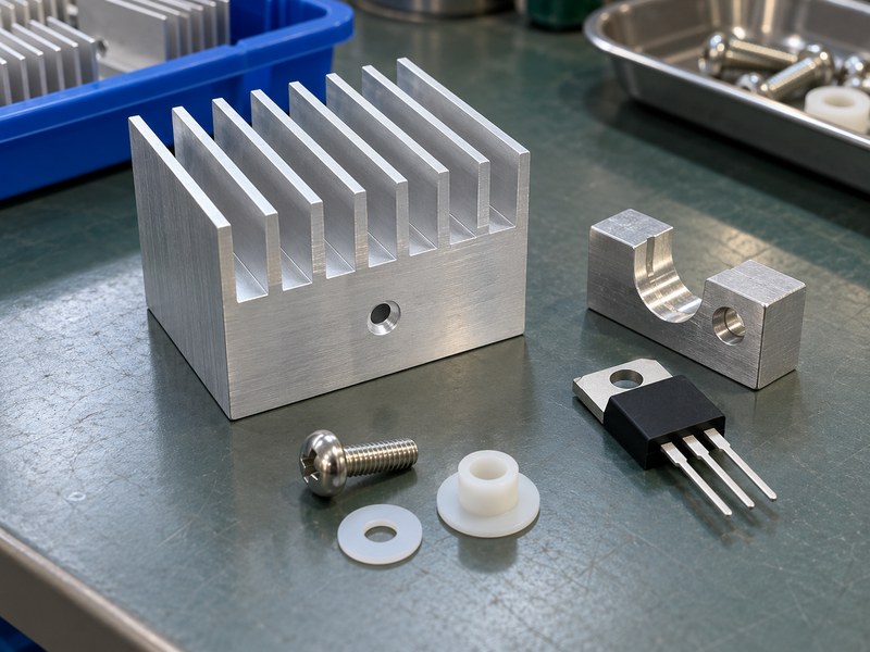
Prepare the DIY voltage regulator heat sink contact face so the package seats on a supported, controlled surface. Locate holes from a defined datum and remove burrs that affect contact. A poorly seated tab can make an otherwise useful shape appear thermally inadequate.
Work from the package drawing
Use the package’s permitted mounting geometry and hole information rather than copying a hole position from a photograph. Keep enough supported contact area around the tab. If the prototype uses a machined land, record the finished geometry and inspect it before interface material hides the surface.
- Verify hole position and fastener access.
- Inspect edges, burrs and local raised areas.
- Check that the package can align without forced leads.
Keep the prototype geometry measurable
Record base thickness, usable contact area and fin orientation so a later supplier can reproduce the idea. If a custom land or pocket proves useful, it can inform a CNC machined heat sink drawing. The bench sample should provide dimensions, rather than becoming an unexplained master shape.
| Contact feature | Inspection question |
|---|---|
| Mounting land | Does the tab seat fully? |
| Hole edge | Is any burr holding the tab off? |
| Alignment | Can the joint assemble without lead stress? |
Verify the contact geometry before judging the prototype’s cooling surface.
5. What electrical insulation does the prototype need?
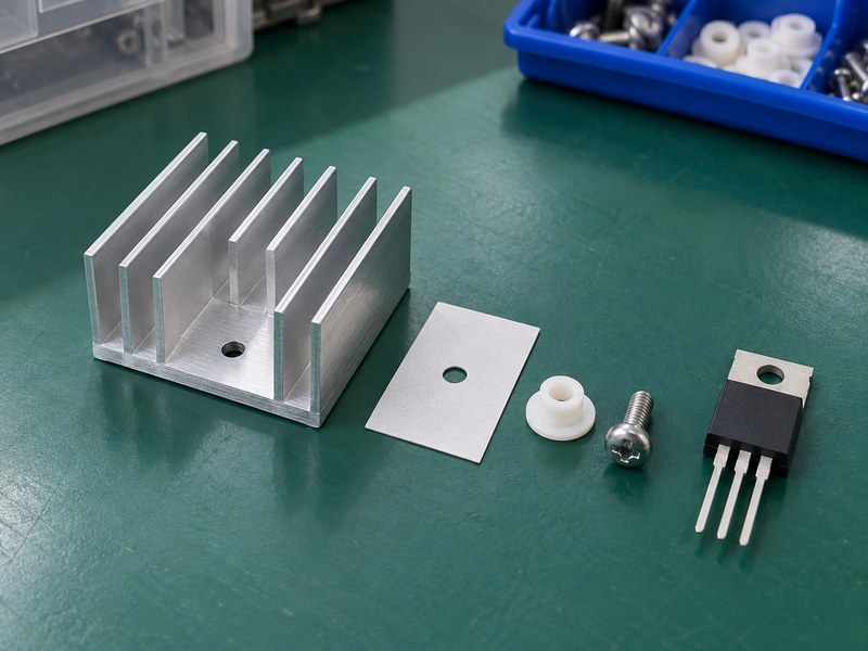
A DIY voltage regulator heat sink needs the same deliberate electrical arrangement as any other mounting part. Check the exact device’s exposed metal connection and its relationship with the sink and chassis. A prototype made from conductive stock can connect circuit nodes through tabs, screws or clips.
Trace the assembled paths
If isolation is required, specify the tab pad and fastener insulation as a complete stack. A pad beneath the tab can be bypassed by a screw touching its hole. Check adjacent leads and the sink’s edges as well, particularly when a hand-made bracket or unfinished contact land changes clearances.
- Identify tab potential from the device documentation.
- Keep leads clear of conductive edges.
- Use the product’s defined electrical acceptance checks.
Retain the thermal interface conditions
Insulating materials add a thermal contribution that belongs in the model and test record. Record their grade, thickness and assembled condition. Comparing an insulated prototype with an uninsulated baseline changes more than geometry, so keep that distinction visible when interpreting the result.
| Prototype route | Required check |
|---|---|
| Tab to stock | Intended contact or specified insulation |
| Screw to tab | Conductive bypass assessment |
| Sink to chassis | Deliberate bonding or isolation |
Test the electrical arrangement that the thermal prototype actually uses.
6. How do you make the mounting repeatable?
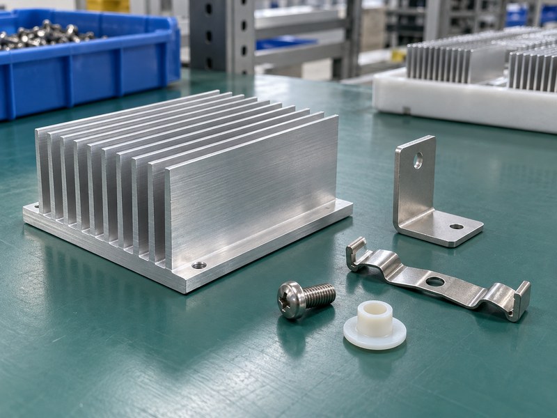
Make DIY voltage regulator heat sink mounting repeatable by controlling interface placement, fastening force and structural support. A comparison loses value if each trial uses a different amount of grease or an unknown screw force. Record the approved mounting process before repeating the thermal test.
Control the assembly variables
Use the package and hardware guidance for screw torque or clip force. A hand-tightened joint can be convenient for initial fit checks, but it does not establish a controlled comparison. Avoid drawing a misaligned tab against the base with the fastener because that can change contact and load the package leads.
- Use the same interface process for comparable trials.
- Record the fastener and force-control method.
- Support the sink without relying on regulator leads.
Build a serviceable test sample
Suitable heat sink mounting hardware can make sample changes easier to repeat. Define which pads or interface materials need replacement after disassembly. Keep those replacement rules consistent between samples so a later run does not inherit a damaged or compressed interface.
| Mounting variable | Control method |
|---|---|
| Interface coverage | Defined application process |
| Fastening | Approved hardware and force |
| Mechanical support | Stable fixture or suitable bracket |
Control the joint before attributing temperature differences to the cooling shape.
7. How should you run a fair thermal comparison?
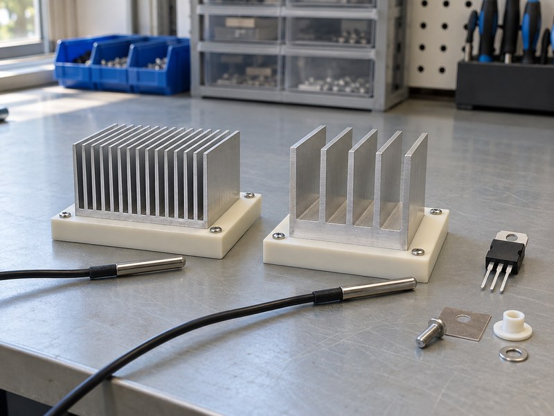
A fair DIY voltage regulator heat sink comparison holds electrical loss, local ambient, orientation and sensor method as consistent as practical. Test the intended installed condition as well as any open-bench comparison. A sample that warms slowly can still reach an unacceptable steady temperature.
Define the measurement procedure
Record where sensors attach and what thermal quantity each reading represents. A sink-surface reading does not directly equal junction temperature, and reflective metal can mislead an infrared camera without suitable treatment. Use package thermal information and measurement methods appropriate for the construction under test.
- Record device loss during each run.
- Measure local air temperature away from hot surfaces.
- Wait for an appropriate sustained-load condition.
Keep the comparison traceable
Retain the mounting revision, pad grade, force and physical orientation with each temperature record. Repeat the baseline when environmental conditions drift enough to affect the comparison. If the final product uses a cover or fan, include that arrangement before deciding which prototype deserves production development.
| Controlled condition | Why it matters |
|---|---|
| Electrical loss | Sets the heat input |
| Local ambient and flow | Sets the air-side boundary |
| Mounting and sensors | Makes temperature comparisons interpretable |
A useful comparison explains both the temperature difference and the conditions that produced it.
8. How do you interpret the temperature results?
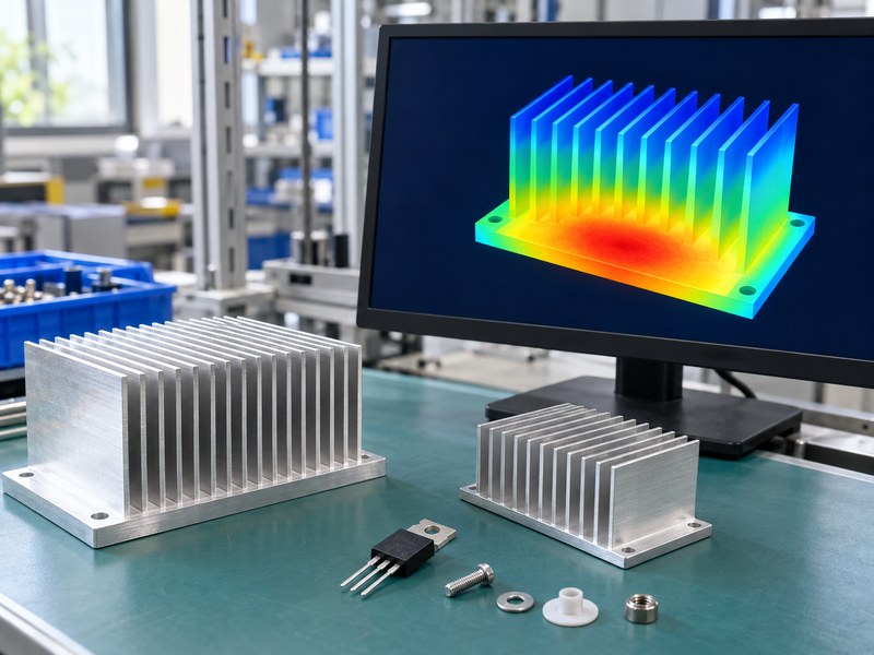
Interpret DIY voltage regulator heat sink results by separating the package-to-base drop from the base-to-air rise. A hot case above a relatively cool base suggests a different investigation from a uniformly hot assembly. A qualitative heat map can guide inspection, but it is not a substitute for recorded temperatures and boundaries.
Investigate the largest drop
Check contact seating, interface coverage and mounting force when the local joint appears to dominate. Check airflow, available cooling area and actual device loss when the base and fins are both hot. Confirm the applicable package metric before translating a measured case temperature into an estimated junction temperature.
- Compare case and local base measurements where suitable.
- Review the assembled interface before changing fin area.
- Check whether local air warms during the run.
Avoid unsupported scaling
Doubling a plate’s mass does not establish twice the cooling capacity, and cutting an extrusion to half length does not guarantee a simple resistance multiplier. Natural convection, spreading and radiation respond to geometry and temperature. Test the proposed change or obtain data relevant to the revised shape.
| Observed behavior | Possible investigation |
|---|---|
| Slow warm-up, high final temperature | Thermal mass versus steady cooling |
| Large case-to-base rise | Contact and local path |
| Hot base and warm inlet air | Air-side capacity and recirculation |
Use the results to choose a specific next change instead of enlarging the sample blindly.
9. When should you convert the prototype into a drawing?
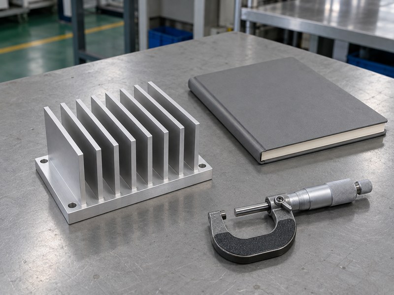
Convert a DIY voltage regulator heat sink into a controlled drawing when its geometry and test result support a clear design decision. The drawing should retain the features that made the sample work. A production supplier needs the contact, cooling and assembly requirements, not merely a request to copy its appearance.
Preserve the functional details
Record contact datums, hole position, base geometry, fin orientation, material and finish. Identify which dimensions need tighter control because they affect thermal contact or electrical clearance. A suitable extruded heat sink may reproduce the concept with controlled machining and finishing operations.
- Attach the prototype’s loss and temperature record.
- State interface and fastening requirements.
- Define the available enclosure and board envelope.
Review the manufacturing proposal
A supplier may propose a different profile, a revised base or another process to meet the same requirement. Compare that proposal against the prototype’s acceptance conditions, rather than assuming visual similarity proves equivalence. Agree on the sample test before approving the revised production construction.
| Prototype record | Drawing requirement |
|---|---|
| Successful contact arrangement | Controlled interface geometry |
| Measured operating result | Defined thermal acceptance |
| Material and mounting process | Reproducible production specification |
Transfer the tested function into the drawing before the hand-made sample becomes the only reference.
10. What should your prototype report contain?
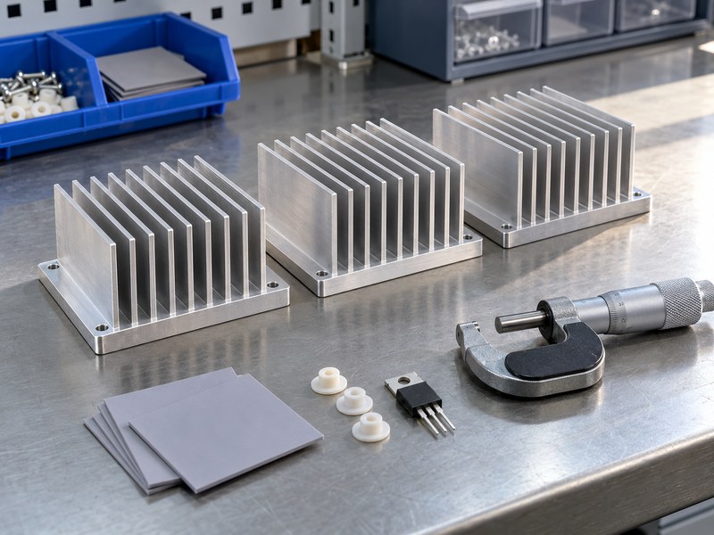
A DIY voltage regulator heat sink report should contain the design question, sample construction, test method and measured result. Distinguish observations from calculated estimates and unresolved assumptions. That makes the work useful for the next engineering and purchasing decision.
Write a repeatable record
Include package identification, device loss, local air temperature, sensor positions, mounting force and interface details. Add drawings or measured dimensions for the sample and baseline. Record any uncontrolled difference that could explain the result, such as changed airflow or a different pad stack.
- State which configuration passed the chosen target.
- Identify what still needs installed-product testing.
- Keep the next sample change specific and measurable.
Prepare the production review
Send the sample drawing, operating record and available envelope when you contact us. We can review a manufacturable cooling and mounting proposal around those inputs. Use a defined acceptance test to confirm the production sample before releasing repeat orders.
| Report section | Decision it supports |
|---|---|
| Construction and method | Whether the result can be reproduced |
| Measurements and model | Whether the thermal target is met |
| Remaining work | Whether another prototype is needed |
Keep the report with the revised drawing and the approved sample record.
Q1: Can I use a metal plate as a temporary heat sink?
Yes, for a controlled prototype if its contact, electrical arrangement and measured temperature suit the test. Its steady cooling still needs verification.
Q2: What’s the best scrap material for a prototype?
Use identifiable stock with a repeatable contact surface. Unknown coatings, alloys and geometry can make the result difficult to interpret or reproduce.
Q3: How do I know if extra weight improved cooling?
Measure the sustained temperature as well as warm-up behavior. Extra mass can delay heating without providing a comparable improvement in steady heat rejection.
Q4: Can I compare two samples with different pads?
You can compare the completed assemblies, but the result will combine geometry and interface changes. Keep that distinction explicit in the test record.
Q5: Can a working prototype go straight into production?
Only after its requirements and acceptance method are transferred into controlled production documents. Review repeatability, assembly and the final installed conditions.