
A voltage regulator needs a heat sink when its package, PCB and surrounding conditions cannot keep junction temperature within the chosen operating target. Decide from loss and temperature rise, then verify the assembled product. Output-current rating, a warm case or a successful short bench test cannot settle the question alone.
1. Does a voltage regulator need a heat sink in every circuit?
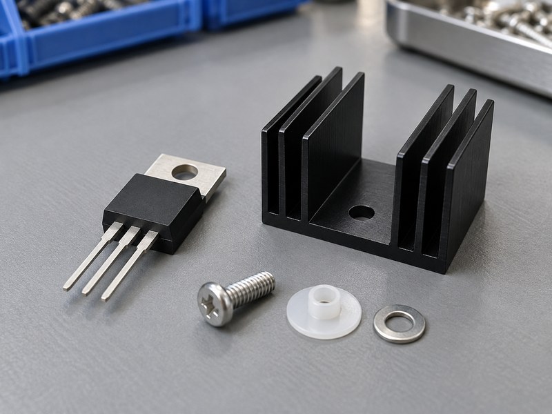
No; “does a voltage regulator need a heat sink” depends on its loss and complete cooling path. Some devices can operate within their targets through package and PCB cooling, while others need an added sink or another design change. Evaluate the intended circuit and installation rather than making the decision from package appearance.
Start with the operating condition
Record input voltage, output voltage, sustained load and local air temperature. Then identify the selected package’s thermal paths and permitted operating limits. A low-current circuit with a large voltage drop can generate more heat than a higher-current circuit with little headroom, so current alone gives an incomplete answer.
- Identify the exact device and package option.
- Calculate the highest credible sustained loss.
- Define a junction-temperature target and its margin.
Choose an evidence-based next step
If the first estimate shows ample margin under relevant conditions, prototype the board without unnecessary hardware and measure it. If it fails, review a suitable board-level heat sink or a change in loss, package or layout. Keep the decision tied to the temperature target you actually need to meet.
| Initial finding | Next action |
|---|---|
| Margin appears sufficient | Verify the complete board |
| Margin is uncertain | Improve inputs or measure a prototype |
| Estimate exceeds target | Review loss or cooling changes |
Use the calculation to choose a useful test or design change.
2. Can a low-current regulator still overheat?
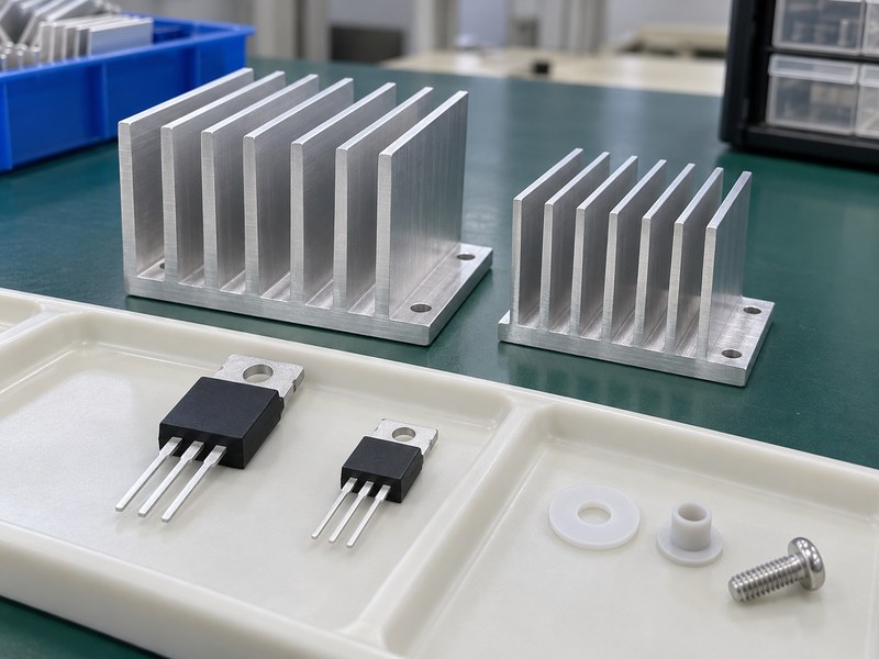
Yes; low current does not answer “does a voltage regulator need a heat sink” without the voltage drop and package path. In a linear regulator, the pass-element loss is approximately voltage drop multiplied by load current, plus the applicable ground-current contribution. A small package can have a limited route into air or board copper.
Compare losses before comparing current labels
For illustration, a linear regulator reducing 24 V to 5 V at 0.1 A has about 1.9 W of pass-element loss. A device reducing 5 V to 3.3 V at 0.5 A has about 0.85 W before ground loss. These examples describe electrical loss only; neither establishes whether the selected package meets its temperature target.
- Keep voltage and current together in the operating table.
- Include ground-current loss using the device’s definition.
- Review package and board behavior separately.
Check the credible maximum
A nominal load may hide periods of sustained higher current or a higher input supply condition. Identify which combinations can occur in service and calculate those states. If the design excludes an adverse combination, keep the circuit or control evidence that supports excluding it.
| Illustrative linear operating point | Main loss |
|---|---|
| 24 V to 5 V at 0.1 A | 1.9 W |
| 5 V to 3.3 V at 0.5 A | 0.85 W |
| 7.5 V to 5 V at 0.1 A | 0.25 W |
The loss calculation explains why a smaller current can still create the larger thermal problem.
3. How much does input voltage affect the decision?
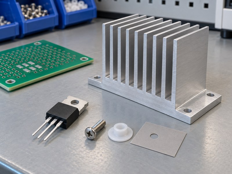
Input voltage strongly affects “does a voltage regulator need a heat sink” for a linear design because extra voltage drop increases pass-element loss. Reducing actual input headroom can lower heat, provided the regulator still meets its electrical requirements. A low-dropout part only provides that opportunity if the circuit uses it.
Review the supply range
Use the voltage at the device under credible load and input conditions. Rectified, battery and regulated rails can each vary differently, so a nominal label may miss the high-loss state. Include ripple and the minimum required headroom before choosing a lower input rail as the thermal fix.
- Check maximum input for heating.
- Check minimum input for regulation and dropout.
- Include relevant startup and transient conditions.
Compare the full electrical change
A preregulator can reduce loss in the linear stage but adds another heat source and changes system behavior. A different supply rail may be simpler if one is available. Compare the completed options using electrical performance, thermal margin and manufacturing requirements, rather than moving heat elsewhere without accounting for it.
| Input-rail question | Required evidence |
|---|---|
| Highest sustained voltage | Worst credible linear-stage loss |
| Lowest operating voltage | Adequate regulation headroom |
| Added preregulator | Its own loss and system effects |
Check both thermal benefit and electrical suitability before changing the supply.
4. Can the package and PCB provide enough cooling?
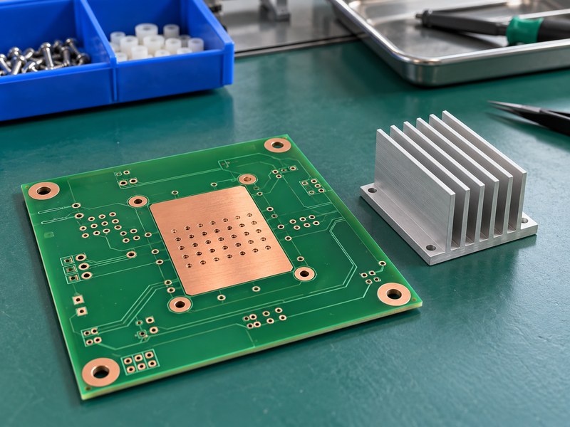
The package and PCB can provide enough cooling in some designs, so they belong in the answer to “does a voltage regulator need a heat sink.” Exposed pads, copper areas, vias and board layers can create deliberate thermal paths. Their effect depends on the actual layout and surrounding assembly.
Use relevant package information
A datasheet’s junction-to-ambient value usually refers to a specified test construction. It is useful context, but it should not be copied into an unrelated board without reviewing the assumptions. Check the manufacturer’s layout guidance and identify whether the package transfers heat mainly through leads, a tab or a soldered pad.
- Review the exact package thermal definitions.
- Check board copper connected with the thermal node.
- Include neighboring sources and enclosure clearances.
Compare hardware and layout changes
More copper or a revised package may avoid an added sink, while another design may benefit from a controlled external contact. An integrated heat sink enclosure is another option when a deliberate conductive wall path fits the product. Test the proposed construction instead of assigning it an assumed cooling credit.
| Existing cooling path | Review point |
|---|---|
| PCB copper | Layout-specific spreading |
| Exposed package pad | Solder and board construction |
| Chassis contact | Defined interface and external cooling |
Decide from the thermal paths the final assembly can actually provide.
5. How do you estimate temperature without an added sink?
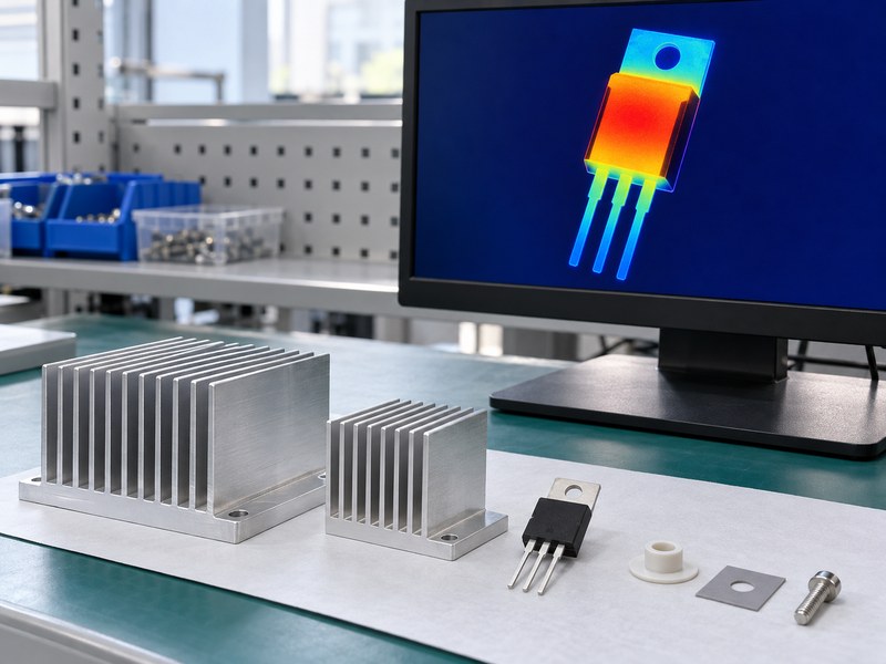
A suitable no-sink estimate helps answer “does a voltage regulator need a heat sink” by comparing predicted junction temperature with the target. For a relevant junction-to-ambient model, TJ ≈ TA + PD × RθJA. The chosen RθJA must represent the package and board conditions well enough for the decision.
Use a clearly labeled screening example
Assume 45°C local air and an illustrative effective RθJA of 50°C/W for the assembly being screened. At 0.3 W, the model predicts a 15°C rise and a 60°C junction; at 2 W, it predicts a 100°C rise and a 145°C junction. Those assumed values demonstrate sensitivity and are not ratings for an unspecified package.
- Replace the assumed resistance with relevant evidence.
- Compare the result with the device-specific target.
- Check uncertainty when the result is near the limit.
Avoid false precision
A prediction of 109.8°C is not a meaningful pass against a 110°C target if loss or local air temperature remains uncertain. Review the spread of credible input values and test the assembly. The estimate should reveal the decision’s sensitivity rather than conceal it behind decimal places.
| Illustrative power | Predicted TJ with the stated assumptions |
|---|---|
| 0.3 W | 60°C |
| 1 W | 95°C |
| 2 W | 145°C |
The same thermal path can pass or fail as the electrical operating point changes.
6. Can an enclosure make an acceptable board overheat?
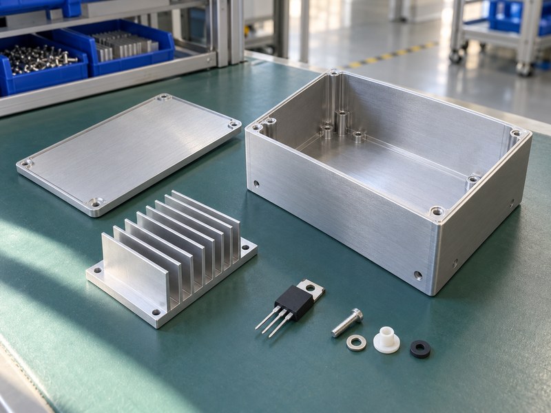
Yes; an enclosure can change “does a voltage regulator need a heat sink” by increasing local air temperature or restricting cooling paths. An open board in room air does not reproduce a warm closed product. Nearby power devices and recirculated exhaust can raise the air temperature reaching the regulator.
Test the installed condition
Fit the intended cover, filters, cables and neighboring loads before the acceptance test. Measure local air near the cooling surface as well as the external chamber condition. A fan-cooled design should be tested with the installed flow restrictions, rather than assigned the fan’s free-air rating as its local cooling condition.
- Use the intended installation orientation.
- Record local inlet and relevant enclosure temperatures.
- Include the product’s sustained neighboring heat loads.
Review conductive enclosure options
A metal housing can help when a controlled interface transfers heat into a wall that can reject it. A loose internal sink in trapped air does not receive that benefit automatically. Define wall contact, insulation and accessible-surface requirements before treating the enclosure as part of the cooling model.
| Open-bench difference | Installed check |
|---|---|
| Warmer internal air | Local temperature measurement |
| Restricted airflow | Final cover and filter test |
| Metal chassis path | Defined contact and external heat rejection |
Repeat the thermal decision using the conditions your customer will operate.
7. Does intermittent operation remove the need for a sink?
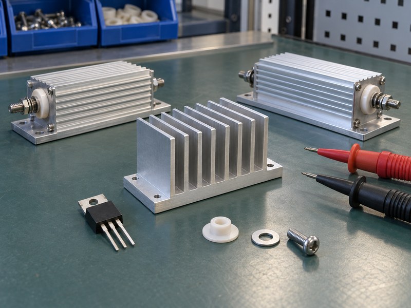
Intermittent operation can change the answer to “does a voltage regulator need a heat sink,” but it does not remove the need to check junction peaks. Average loss describes one part of the thermal behavior. Pulse duration, repetition and the initial temperature determine whether the junction experiences a higher short-term peak.
Review the actual load sequence
A single short pulse from a cool board differs from a repeated pulse train after a long warm period. Use transient thermal information where appropriate and available, or validate the required sequence with a suitable measurement method. Also keep electrical current limits and safe-operating conditions in the review.
- Record pulse amplitude, duration and repetition.
- Identify sustained states between pulses.
- Test from a credible warm initial condition.
Keep the thermal mass distinction
A heavy cooling part can delay temperature rise without providing sufficient steady heat rejection. That may help a defined transient application, but it does not establish suitability for a longer duty cycle. Review any product revision that extends operating time or increases repetition.
| Operating pattern | Needed assessment |
|---|---|
| Sustained load | Steady thermal behavior |
| Isolated pulse | Relevant transient response |
| Repeated duty cycle | Peak and accumulated heating |
Use the operating time history when deciding whether extra cooling is needed.
8. Which symptoms justify a thermal investigation?
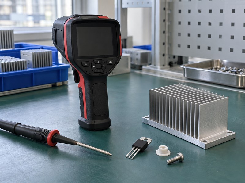
Thermal shutdown, load-dependent resets or temperature-related output changes justify investigating “does a voltage regulator need a heat sink.” They do not prove that the sink size is the cause. Electrical supply behavior, contact, airflow and the regulator’s protection functions also need review.
Measure before assigning the cause
Record voltage, current and temperature around the event. Confirm whether the regulator is entering a documented protection state or whether another circuit condition explains the symptom. A case that feels warm is not a reliable junction-temperature measurement, and a cool sink does not establish good contact.
- Check the electrical operating state during the symptom.
- Measure relevant package, base and local air temperatures.
- Inspect interface seating and intended heat paths.
Distinguish local and air-side problems
If an added sink stays cool while the package is hot, inspect the package-to-base path before choosing larger fins. If both are hot, review total loss, local air and cooling capacity. Heat sink mounting hardware and interface controls can be as relevant as the profile’s outer dimensions.
| Observation | Investigation |
|---|---|
| Shutdown cycling | Loss, protection state and temperatures |
| Hot package, cooler base | Local mounting path |
| Hot assembly | Air-side cooling and heat input |
Use the symptom to choose measurements, then use the measurements to choose a fix.
9. Which change should you try before adding hardware?
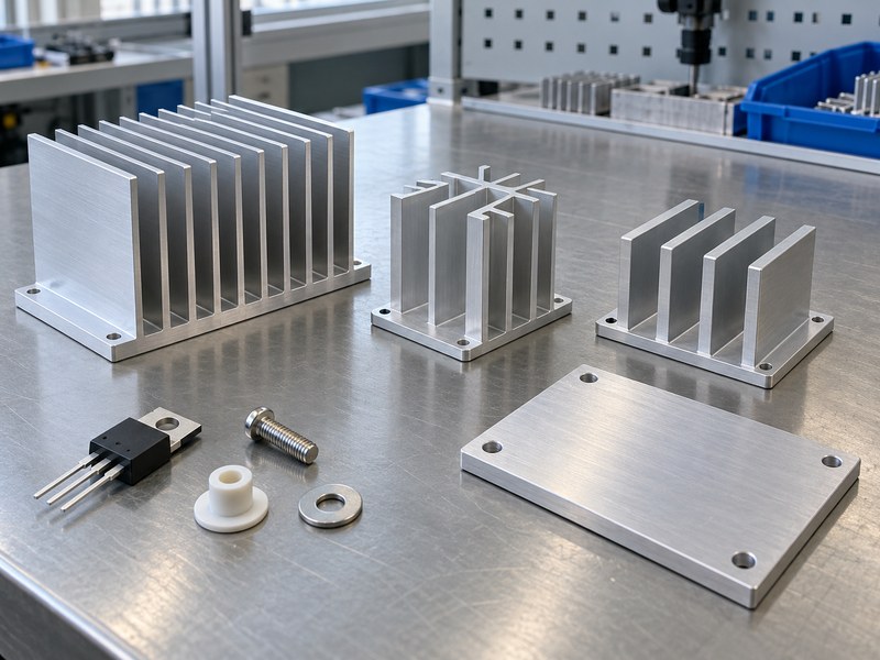
Review loss, package and existing thermal paths before settling “does a voltage regulator need a heat sink” by adding the largest available part. Lower input headroom, a suitable package or an improved board path may solve the requirement. An external sink remains appropriate when its defined contact and cooling surface meet the target.
Compare specific alternatives
Write down the mechanism each proposed change addresses. Lower input voltage reduces linear-stage heat, while improved contact reduces a local resistance and added fin area changes the air-side path. Comparing those mechanisms helps avoid spending space or assembly effort on a resistance that was not limiting the design.
- Calculate the loss after an electrical change.
- Recheck the package path after a component change.
- Test the installed boundary after an airflow change.
Choose a manufacturable cooling option
A standard extruded heat sink with controlled mounting may meet the requirement without a complex custom structure. Another assembly may need a machined contact or chassis path. Compare the completed options using the same operating target and acceptance test.
| Proposed change | Main effect |
|---|---|
| Lower linear-stage voltage drop | Less heat generation |
| Improved interface | Smaller local temperature drop |
| Added cooling surface | Better heat rejection under suitable conditions |
Choose the change that addresses the measured or calculated limiting path.
10. How do you confirm the final decision?
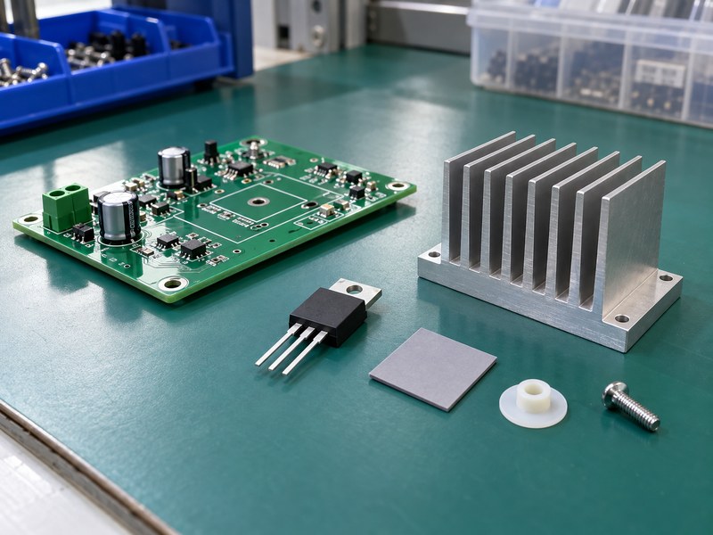
Confirm “does a voltage regulator need a heat sink” by testing the selected assembly against its documented operating target. A no-sink design and an added-sink design both need evidence under credible loss and ambient conditions. Record the configuration so production and later revisions can reproduce the result.
Retain the acceptance evidence
Keep the loss calculation, package information, local temperature measurements and relevant test sequence together. State the junction estimate method and its limitations when junction temperature is not measured directly. Include enclosure and airflow details so another engineer can understand which operating range the result supports.
- Record the selected design and remaining temperature margin.
- Identify approved package and interface substitutions.
- Define changes that trigger another thermal review.
Prepare the engineering review
Send your device identification, loss calculation, local ambient and available envelope when you contact us. We can discuss whether a board-level sink, extrusion or revised mounting path suits those requirements. Agree on the prototype acceptance test before releasing the configuration for repeat production.
| Final decision record | Required content |
|---|---|
| Electrical state | Supported input and load range |
| Thermal result | Defined target and measured conditions |
| Assembly | Controlled package, interface and cooling arrangement |
Revisit the decision whenever loss or installed cooling conditions change.
Q1: Can I leave a regulator without a sink if it works briefly?
Only after validating the intended operating duration and temperature range. A short test may end before the assembly reaches its sustained temperature.
Q2: What’s the best sign that a sink is needed?
The strongest evidence is an inadequate junction-temperature margin under credible conditions. Calculate the loss and thermal path, then verify the complete assembly.
Q3: How do I know if a warm case is acceptable?
Use a suitable measurement and the package’s thermal information. Touch alone cannot establish junction temperature or the device’s operating margin.
Q4: Can better PCB copper remove the need for a sink?
It can in some designs. The result depends on package attachment, layout, stack-up and surroundings, so validate the revised board.
Q5: Can I rely on shutdown to prevent thermal problems?
Do not use shutdown cycling as normal thermal control without a specifically validated design. Correct the loss or cooling arrangement so intended operation stays within its target.