
The right heat sink size for a voltage regulator is the geometry that meets its thermal resistance target within the installed envelope and mounting limits. Calculate the required performance before choosing length, height or fin count. A universal dimension cannot account for different losses, package contacts, air temperatures and airflow conditions.
1. What size heat sink for voltage regulator applications?
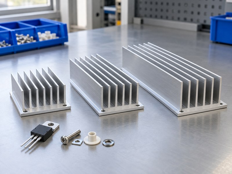
To decide what size heat sink for voltage regulator applications will work, start with heat loss and allowed temperature rise. Those inputs give a maximum thermal resistance under defined conditions. Supplier data or a suitable model then connects that requirement with a candidate geometry.
Separate performance from outer dimensions
Two parts with the same length, width and height can have different base spreading, fin area and air resistance. Their mounting interfaces may also differ. A dimension such as “25 mm heat sink” is therefore a packaging description, rather than proof that the part can cool the selected device.
- Calculate the device’s credible sustained loss.
- Define local ambient and the junction target.
- Identify package and interface temperature drops.
Define the useful design result
The result should identify an acceptable geometry, orientation and mounting stack together. A suitable board-level heat sink may be compact when loss is low and contact is effective. Another device with the same package outline may need substantially different cooling because its operating point differs.
| Design input | What it determines |
|---|---|
| Loss and allowed rise | Thermal resistance budget |
| Package footprint | Contact and spreading requirement |
| Envelope and airflow | Usable cooling geometry |
Use dimensions to satisfy the thermal requirement, rather than using dimensions as the requirement itself.
2. How do you calculate the performance target first?
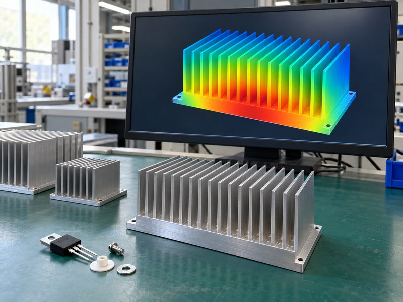
A thermal budget gives the performance target behind “what size heat sink for voltage regulator.” For a suitable steady-state series model, RθSA ≤ (TJ,target − TA)/PD − RθJC − RθCS. The package thermal value must match the surface that connects with the sink.
Work with declared assumptions
Suppose an example device dissipates 3 W in 45°C local air with a 110°C junction target. Its total resistance budget is approximately 21.7°C/W. If the applicable package and interface paths total an assumed 5°C/W, the sink needs about 16.7°C/W or less under the intended installation conditions.
- Replace example values with the selected device’s information.
- Include the actual interface material and assembly conditions.
- Keep a stated margin for uncertainty and operating variation.
Screen the available shapes
A candidate rated 15°C/W in matching conditions may deserve prototype evaluation, while one rated only under stronger forced airflow may not. Do not select by the smallest catalog number without checking what that number describes. Geometry selection begins after the rating’s test or model conditions are understood.
| Illustrative budget item | Result |
|---|---|
| Available junction rise | 65°C |
| Total allowed resistance | About 21.7°C/W |
| Remaining sink allowance | About 16.7°C/W |
The calculated allowance gives supplier proposals a common performance target.
3. Which envelope dimensions should you reserve?
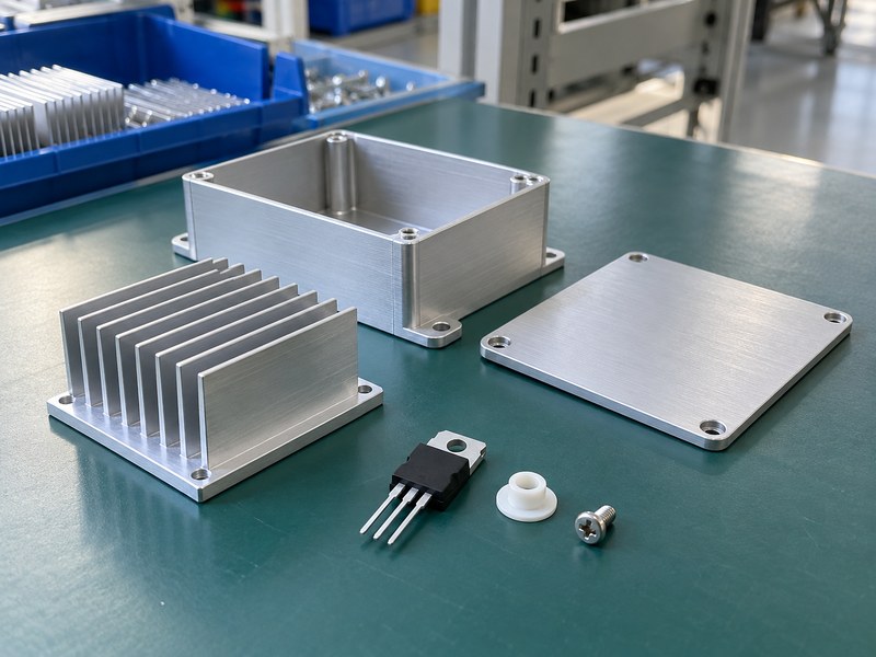
Reserve an installed envelope when deciding what size heat sink for voltage regulator hardware can fit. Include the part’s geometry, assembly access, airflow space and tolerance stack. A sink that fits nominal CAD dimensions may still clash with a cover or leave no route for warmed air to escape.
Include surrounding components
Review connector access, cable routing, adjacent components and tool clearance around the mounting point. Fin height must allow for the actual cover position and permitted board movement. Length and width should leave room for insulating hardware, supports and any required electrical clearances.
- Check the finished enclosure and board tolerances.
- Leave access for assembly and service tools.
- Keep inlet and outlet paths outside the blocked envelope.
Distinguish keep-outs from contact areas
A heat sink enclosure can combine cooling and housing geometry when a deliberate conductive path suits the product. For a separate internal sink, define the contact land and surrounding keep-outs independently. Space occupied by fins cannot automatically be counted as useful cooling area when a wall blocks the airflow.
| Envelope item | Clearance to review |
|---|---|
| Fin height | Cover and board movement |
| Base footprint | Components, screws and electrical spacing |
| Air path | Inlet, channels and outlet |
Reserve the space required by the installed thermal system, including its access and airflow.
4. How large should the base and contact land be?
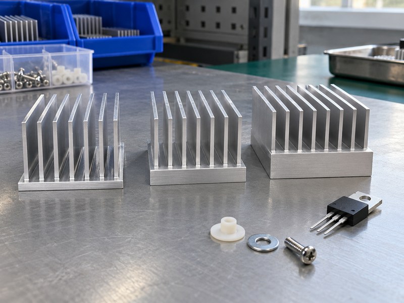
Base size should support the package contact and spread heat into useful cooling surface when answering “what size heat sink for voltage regulator.” A small tab on a large thin base can create a local spreading drop. Increasing the footprint without reviewing that path may add area that receives little heat.
Match the contact geometry
The mounting land should support the intended package surface without burrs or unsupported edges. Locate holes from controlled datums and preserve the required contact flatness after finishing. A custom land or step can suit CNC machined heat sinks when the package or board height prevents a simple flat extrusion base.
- Show the package footprint on the sink drawing.
- Review base thickness and spreading distance together.
- Keep fastener holes from weakening the contact area.
Check the local temperature distribution
A spatial model or measurements can reveal whether the base spreads heat effectively into the fins. If the mounting region is much hotter than distant areas, compare base geometry and material before adding more remote fin area. Keep interface resistance separate so a poor joint is not mistaken for a spreading problem.
| Base feature | Design purpose |
|---|---|
| Supported contact land | Repeatable package seating |
| Suitable thickness | Heat spreading and stiffness |
| Controlled hole pattern | Alignment without forced leads |
Size the base around the heat source and its path into the available fins.
5. How do fin height and spacing affect the result?
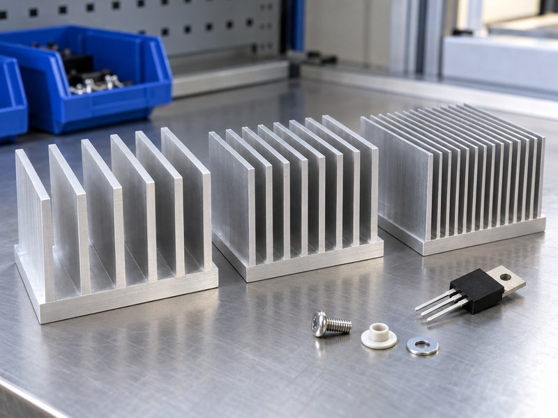
Fin height and spacing affect both exposed area and airflow when selecting what size heat sink for voltage regulator cooling to use. More fins do not guarantee a lower installed temperature. Closely spaced channels can restrict natural convection, increase flow resistance or collect contamination.
Review the cooling mode
A fanless design needs a geometry that supports buoyant air movement in its actual orientation. A forced-air design needs usable flow through the channels at the installed pressure and restriction conditions. Compare candidate profiles using the appropriate thermal data instead of assuming the densest fin pattern is best.
- Identify natural or forced convection as the intended mode.
- Review channel openings and nearby wall clearance.
- Include contamination and cleaning requirements where relevant.
Include base and fin efficiency
Tall fins add area, but heat must conduct into them from the base. Material, thickness and temperature distribution influence how effectively that area contributes. Compare the full profile under the required operating condition rather than using total surface area as the only selection metric.
| Fin change | Tradeoff to review |
|---|---|
| Taller fins | Area, conduction and available height |
| Smaller spacing | Area versus airflow restriction |
| Thinner fins | Weight, efficiency and manufacturing limits |
Choose a profile whose surface remains thermally useful and exposed to the intended cooling flow.
6. Can you scale a rating by cutting an extrusion shorter?
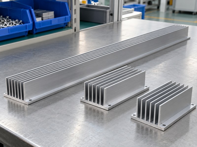
Do not assume a simple linear scaling rule when deciding what size heat sink for voltage regulator use can be cut from an extrusion. Length changes surface area, spreading distance and airflow behavior together. A rating for a long sample may not transfer accurately to a short piece with the same cross-section.
Request data for the proposed length
Ask the supplier for thermal information relevant to the actual length, source footprint and orientation. Some product families provide length-dependent curves or a suitable model, while others need a sample test. Keep any extrapolation visible in the design record instead of presenting it as a measured rating.
- Identify the rated sample length and heat-source size.
- Request the proposed cut length’s performance basis.
- Review mounting features that remove base or fin material.
Compare practical profile options
A different cross-section may fit the requirement better than extending a profile whose height or spacing is unsuitable. Extruded heat sinks offer a production route when a practical section and controlled machining meet the design. Compare finished candidates using the same acceptance conditions.
| Length-related item | Question for the supplier |
|---|---|
| Catalog rating | Which sample length was used? |
| Proposed cut length | What evidence supports its resistance? |
| Machined features | Do they alter the thermal path? |
Obtain a performance basis for the delivered length, rather than scaling an unrelated number blindly.
7. How does orientation change the usable size?
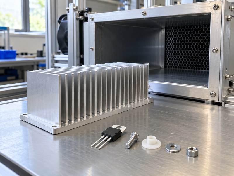
Orientation changes the cooling conditions behind “what size heat sink for voltage regulator.” A part that meets its target with open vertical channels may behave differently when rotated near a cover. The useful size is the geometry that performs in the intended installation, rather than in an easier test position.
Check the complete airflow route
For forced air, inspect how flow reaches the sink and where it exits. Bypass gaps, filters and neighboring components can divert air around the channels. Local inlet air may already be heated by another source, so use that temperature in the thermal budget rather than room temperature alone.
- Record the actual board and fin orientation.
- Include cover, filter and cable restrictions.
- Check local air near the heated region.
Preserve the tested arrangement
If the product can operate in several mounting orientations, evaluate the relevant worst conditions. Keep the required installation limits with the product and assembly documentation. A later enclosure revision that changes the air route can invalidate a previously acceptable profile even when its dimensions stay the same.
| Installation change | Thermal review |
|---|---|
| Board rotation | Natural-convection path |
| New cover or filter | Restriction and recirculation |
| Upstream heat source | Local inlet temperature |
Keep the profile’s rating tied to the orientation and air route it will actually use.
8. How much mass can the board and package support?
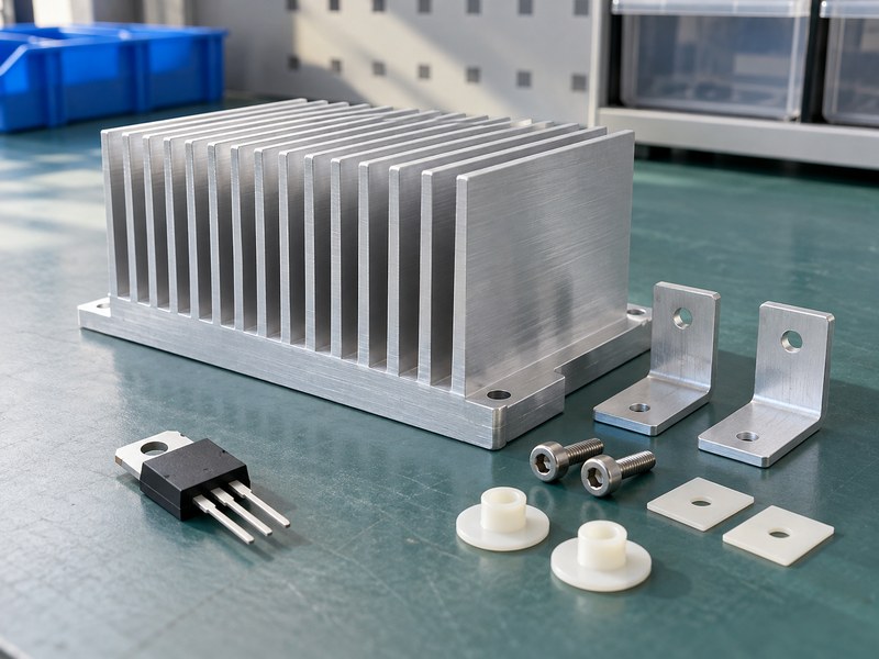
Mechanical support limits the answer to what size heat sink for voltage regulator assemblies can use. A heavier part can add shipping, handling and vibration loads even when it improves cooling. The device leads and solder joints should not become the unintended support for a large profile.
Review the load path
Identify where the sink’s weight and fastening reactions enter the PCB or enclosure. A bracket, standoff or chassis support may be needed, depending on the mass and environment. Account for relative expansion and tolerances so the supported sink can maintain contact without forcing the package out of alignment.
- Check board support near the mounting points.
- Keep leads clear of bending and structural loads.
- Review assembly access and service removal.
Control mounting force
Heat sink mounting hardware should maintain the approved contact force without damaging the tab, interface or board. A larger base may need different support or fastening details from a small individual sink. Include those changes in the prototype, rather than testing an assembly that production cannot reproduce.
| Mechanical factor | Design check |
|---|---|
| Added mass | Support during service and handling |
| Fastening reaction | Board and package loading |
| Thermal expansion | Contact stability and lead stress |
Choose a size that the whole assembly can carry and mount consistently.
9. What should a size-focused supplier request include?
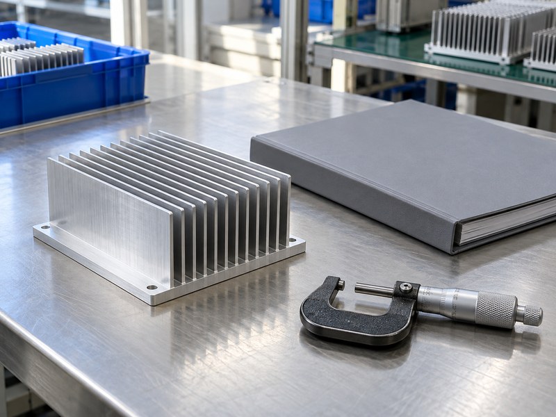
A supplier request for what size heat sink for voltage regulator service to use should include performance, envelope and contact requirements. Outer dimensions alone leave the thermal job undefined. Provide the heat load, local ambient, orientation and interface assumptions with the drawing.
Separate fixed constraints from preferences
Mark dimensions that cannot change because of the board, connectors or enclosure. Identify where a supplier can propose another fin height, cut length or mounting feature. That distinction lets the supplier compare practical sections without treating an early prototype’s every dimension as a functional requirement.
- State maximum thermal resistance and its conditions.
- Provide package and contact drawings.
- Identify mass, support and clearance limits.
Agree on sample evidence
Ask how the candidate’s resistance was measured or modeled and which conditions apply. Define the prototype acceptance method before ordering a production quantity. If a proposed profile changes the mounting interface, include electrical isolation and mechanical checks in addition to the temperature test.
| RFQ line | Required content |
|---|---|
| Performance | Loss, temperature target and cooling conditions |
| Envelope | Fixed limits and permitted changes |
| Contact | Footprint, holes and interface stack |
Give suppliers room to propose a workable geometry while keeping acceptance conditions fixed.
10. How do you confirm the chosen size fits and cools?
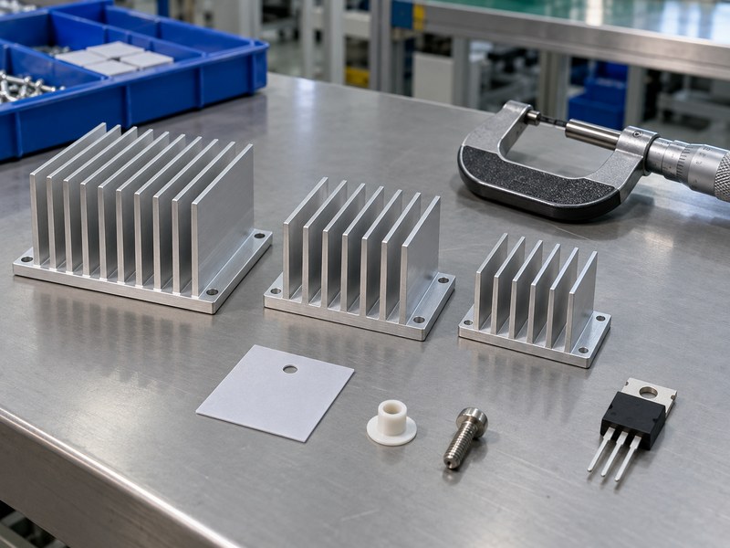
Confirm what size heat sink for voltage regulator hardware works by inspecting fit and testing thermal behavior in the same final assembly. A mechanical pass does not establish cooling, and a thermal bench pass does not establish enclosure clearance. Keep both results linked to the released geometry and mounting stack.
Inspect the assembled prototype
Check contact seating, insulation, lead clearance, fastening access and cover fit at relevant tolerances. Then test the intended electrical operating states with the final airflow and orientation. Record package, base and local air temperatures using suitable methods and thermal metrics for the selected device.
- Compare results with the stated junction target.
- Retain the exact pad and hardware configuration.
- Identify geometry or cooling changes that require retesting.
Prepare the release review
Send the thermal budget, package drawing and available envelope when you contact us. We can discuss a practical profile, cut length and mounting arrangement against those constraints. Approve the sample against the agreed fit and thermal tests before releasing repeat orders.
| Final acceptance | Required evidence |
|---|---|
| Fit | Controlled geometry and installed clearance |
| Contact | Approved interface and mounting process |
| Cooling | Defined load, ambient and temperature result |
Release the size together with the operating conditions that make it acceptable.
Q1: Can I choose a heat sink from its length alone?
No. Base geometry, fin arrangement, contact and installed cooling conditions affect performance. Match a documented thermal rating with your assembly requirements.
Q2: What’s the best fin spacing for passive cooling?
Use spacing supported by the intended profile and orientation. Very dense fins can restrict natural convection, so compare relevant data or test the installed sample.
Q3: How do I know whether a thicker base will help?
Check whether local spreading is limiting the design. A thicker base may improve that path, but it does not resolve a poor interface or inadequate air-side cooling.
Q4: Can I halve a catalog sink and double its resistance?
Do not assume that rule is accurate. Length changes spreading and airflow as well as area; obtain relevant length data or test the revised part.
Q5: Can I approve the size with the enclosure open?
An open test can support development, but final acceptance needs the intended cover, orientation and cooling arrangement. Those conditions can change the local thermal result.