
Base your flexible heat-pipe choice on whether it will be formed once or must survive repeated movement. Those are different purchasing requirements. A copper tube that bends during assembly can lose performance or fatigue if a hinge keeps flexing it in service. Your flexible heat pipe specification should tie construction, supports and tests to the equipment’s actual duty.
1. What does flexible heat pipe mean in a specification?
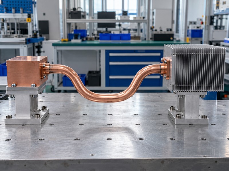
The term flexible heat pipe needs a written movement definition before it can support a purchase specification. Some products permit controlled forming into a permanent route, while specialty constructions accommodate relative motion between the source and sink. A sales description that says bendable does not establish a safe motion range, a cycle life, or an allowable load on either attachment.
Which kind of flexibility does your equipment need?
Describe what moves, when it moves, and whether the pipe returns to its original position. Adjustment during initial assembly differs from opening a service cover, and both differ from continuous vibration or articulation during operation. State whether thermal performance is required while moving, after movement, or in a set of stationary positions so the supplier can assess the correct duty.
- Separate initial forming from repeated service movement.
- Give the source and sink positions throughout travel.
- Identify the temperatures and heat load during motion.
| Requirement | Meaning |
|---|---|
| Form once | Permanent geometry after controlled shaping |
| Occasional repositioning | Defined maintenance movement |
| Cyclic flex | Repeated motion with a qualification profile |
Use the movement category in the RFQ title so bidders cannot substitute assembly formability for an operating fatigue requirement.
2. Can an ordinary copper heat pipe bend repeatedly?
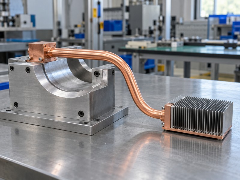
A conventional copper device sold as a flexible heat pipe needs construction-specific evidence before you assign repeated bending duty. Forming plastically strains the wall and can disturb the internal wick, while recurring deformation can introduce fatigue at a bend or attachment. A successful single adjustment establishes performance in that configuration; repeated service motion needs separate lifetime evidence.
Why does a successful hand bend prove so little?
A visible copper surface hides the condition of the wick and vapor passage inside. The pipe may remain sealed yet return liquid less effectively, or it may work at a modest load while losing margin at the intended operating point. Reversing a bend to correct fit adds another strain history, so uncontrolled straightening and rebending should never become an undocumented production step.
- Use the manufacturer’s permitted forming procedure.
- Keep assembly adjustments within the approved allowance.
- Quarantine parts with kinks, dents, or unapproved rework.
| Observation | What remains unproven |
|---|---|
| Pipe stays sealed | Internal wick condition |
| Low-load test passes | Required-load margin |
| One bend succeeds | Repeated-motion durability |
For a stationary enclosure, prefer a factory-formed route and controlled supports instead of asking operators to reshape delivered assemblies.
3. How does bending change heat pipe performance?
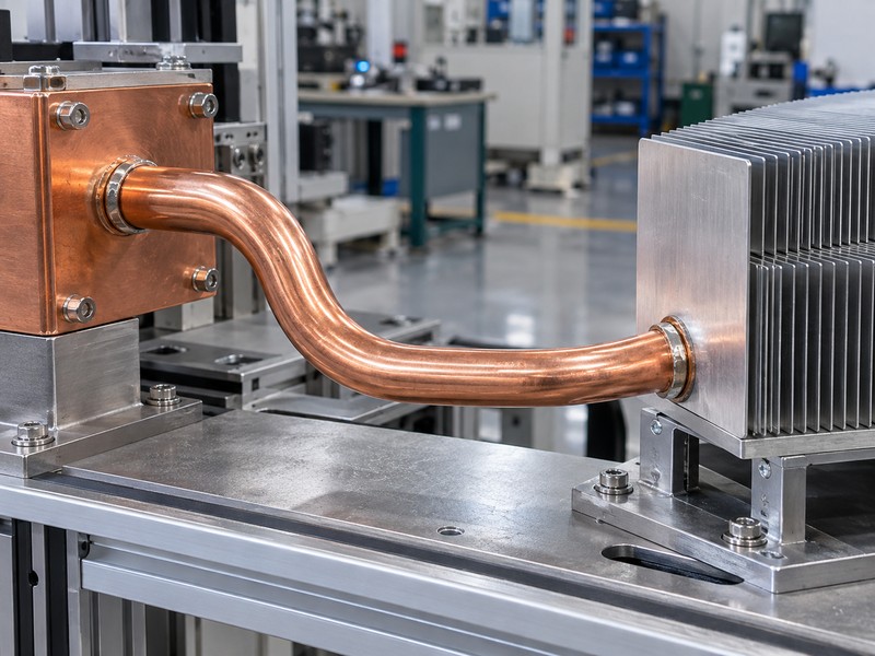
Bending a flexible heat pipe can change its cross-section and internal liquid-return path. The result depends on construction, bend geometry, location, and orientation, so there is no universal percentage loss for every curve. A route that combines bending with flattening also changes the vapor space, making separate straight-pipe and bend rules an uncertain basis for final capacity.
Which internal changes need consideration?
The wick must stay effective enough to return condensate to the heated region, and the vapor needs an adequate passage toward the condenser. Bending can alter both paths through local deformation or wick displacement, with the effect varying across wick designs. Evaluate the full route at relevant temperatures and attitudes, especially when gravity opposes liquid return or the design approaches its transport limit.
- Keep evaporator and condenser contact zones well defined.
- Identify combined bends, flattening, and short transitions.
- Ask for data on the finished geometry.
| Forming feature | Possible consequence |
|---|---|
| Local ovality | Smaller vapor passage |
| Wick disturbance | Changed liquid return |
| Different elevation | Different gravity contribution |
Treat formed-state thermal performance as the acceptance basis and use generic bending guidance only to screen early packaging options.
4. How should you choose the bend radius?
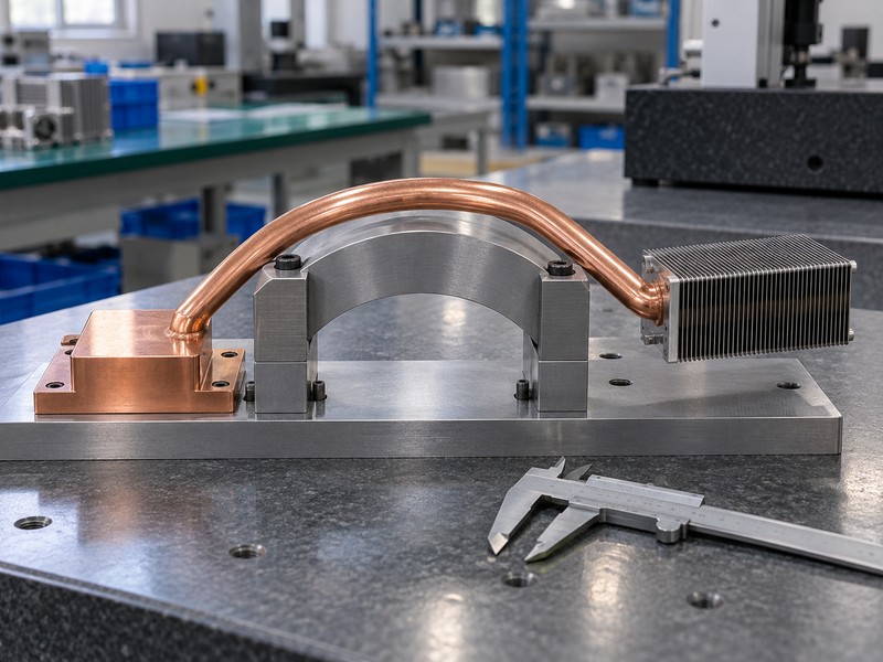
Choose the flexible heat pipe bend radius with the selected supplier and construction rather than applying one ratio to every tube. Outside diameter, wall condition, wick, tooling, bend angle, and nearby flattened zones influence what can be formed successfully. State whether the drawing radius follows the tube centerline or inner surface, since the same written value can otherwise describe different geometry.
What belongs in the forming drawing?
Show tangent points, bend planes, straight gripping lengths, and the allowed route envelope. Ask the supplier to confirm process sequence and inspect the combination of features, because two individually feasible operations can become difficult when their tooling zones overlap. Leave room for a broader route early in packaging if the proposed minimum radius requires unnecessary development risk or reduces thermal margin.
- Use a named radius convention throughout the drawing.
- Identify locations where field adjustment is prohibited.
- Confirm tolerances after the approved forming process.
| Drawing item | Removes this ambiguity |
|---|---|
| Centerline radius | Which part of the curve is measured |
| Bend plane | Direction of the finished route |
| Protected zone | Where tools and adjustment may act |
Freeze the radius after the supplier has reviewed the complete geometry, then validate a sample made by the proposed production method.
5. What construction can accommodate repeated movement?
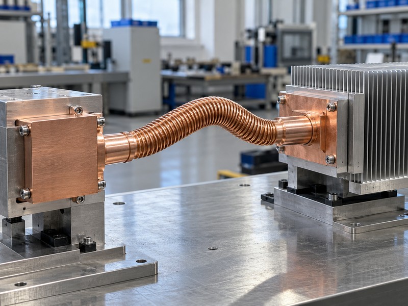
A flexible heat pipe intended for repeated movement needs a construction developed for that duty, potentially including a bellows section and a compatible flexible wick. The compliant section must preserve the sealed fluid path while the internal return structure continues to function. Such devices require their own thermal and mechanical evidence; a drawing that adds corrugations to a copper tube is insufficient.
Which supplier evidence should match your motion?
Request qualification conditions for the proposed architecture, including displacement, angle, temperature, orientation, and end constraints. A test result from another device can explain the technology without proving the offered assembly’s life. Keep specialty motion hardware as a separate sourcing question: conventional formed copper-water assemblies do not establish a supplier’s capability to provide bellows devices or application-specific aerospace qualification.
- Identify the compliant region and its working envelope.
- Check the internal return path throughout movement.
- Compare the tested fixture with your actual attachments.
| Specialty feature | Evidence needed |
|---|---|
| Flexible envelope | Fatigue and seal integrity |
| Flexible wick | Transport throughout the motion range |
| End attachments | Loads and qualified boundary conditions |
Select a specialty construction only after its documented movement envelope covers the equipment duty and the offered configuration has a defined approval route.
6. How should you support the source and condenser ends?
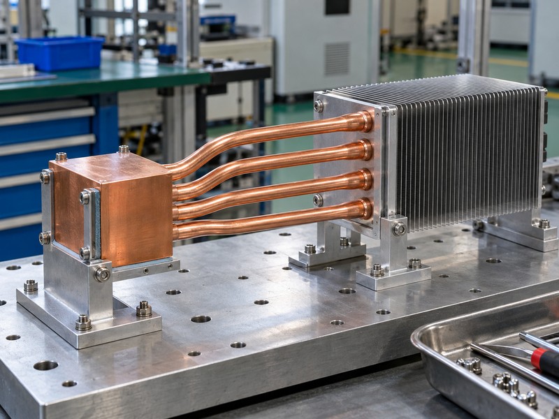
Support a flexible heat pipe so the intended compliant region absorbs movement and the thermal contacts remain stable. The source block and condenser should have independent mechanical load paths suited to their mass and environment. Do not rely on the sealed tube to pull misaligned parts together, restrain a heavy fin stack, or compensate for a poor mounting tolerance stack.
Where should strain relief begin?
Review heat sink mounting hardware with the entire travel path, including fastener access and nearby cable or hose loads. Locate constraints so they do not concentrate bending at a joint edge or transfer motion into the device package. Where thermal pads bridge a gap, control their compression separately; pad compliance cannot qualify the pipe for repeated movement.
- Support heavy thermal blocks and remote fin structures.
- Preserve clearance throughout the full motion envelope.
- Define clamp locations, contact loads, and assembly order.
| Support detail | Function |
|---|---|
| Source attachment | Maintain contact within package limits |
| Condenser bracket | Carry mass and external loads |
| Motion clearance | Prevent rubbing and local overbending |
Check attachment forces at both travel extremes before accepting a route that looks relaxed only at its central position.
7. Which motion details belong in a fatigue requirement?
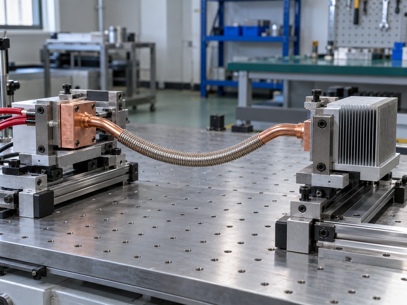
A flexible heat pipe fatigue requirement should describe the complete movement history and environment. Include translation, rotation, torsion, rate, dwell, and how often each motion occurs during operation, installation, and servicing. Specify the end constraints because an assembly with freely rotating blocks can experience very different local strain from the same nominal travel with rigid attachments.
How should you build a representative test profile?
Map the equipment duty into distinct motion events and identify combinations that may be more severe than any isolated movement. Test the relevant temperature and heat-load conditions rather than applying an unexplained cycle count at room temperature. Set thermal, leak-integrity, and mechanical acceptance criteria before the test, with intermediate inspections when they help identify how degradation develops.
- Include assembly and maintenance cycles in the duty history.
- Record the fixture geometry and constraint locations.
- Define acceptable thermal drift and visible damage criteria.
| Duty input | Why the test needs it |
|---|---|
| Amplitude and direction | Establish local deformation |
| Rate and dwell | Reproduce movement timing |
| Thermal condition | Represent operating stress and transport |
Agree on a representative duty profile and its qualification rationale instead of accepting an impressive cycle number without matching test conditions.
8. How do you test thermal performance after forming?
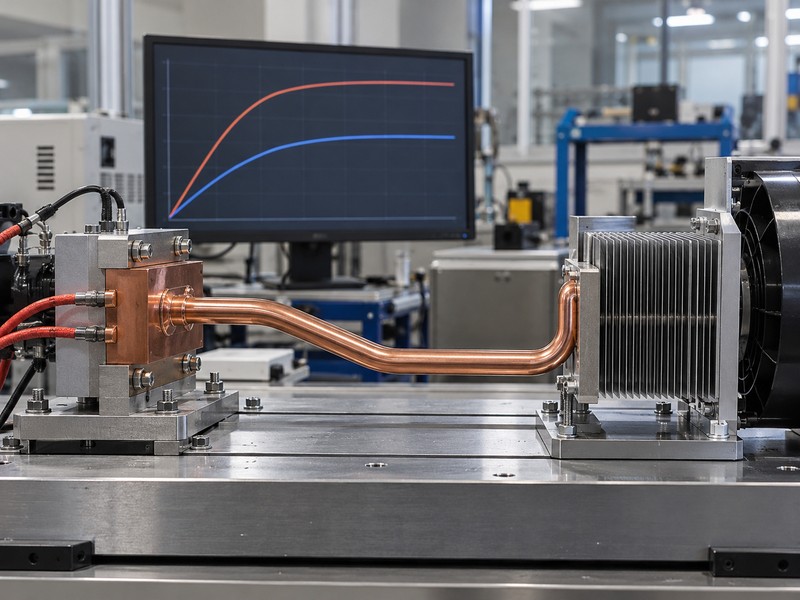
Test the flexible heat pipe in its final formed configuration using defined heat input, cooling conditions, and measurement locations. Compare results at matched temperatures and orientations so a fixture change does not masquerade as a forming effect. If the device will move in operation, include the required positions and the agreed motion condition rather than testing only a convenient straight configuration.
What measurements reveal a loss of margin?
Record evaporator and condenser temperatures over the specified load range, with a stable cooling boundary and an allowance for fixture heat loss. Thermal resistance, calculated from a declared temperature difference divided by transported heat, can help compare matched configurations. A rapid temperature rise at increasing load needs investigation of the pipe, contacts, and cooling fixture before assigning the cause to a particular internal limit.
- Use matched sensor positions before and after exposure.
- Define steady state and measurement uncertainty.
- Repeat agreed thermal points after motion qualification.
| Test stage | Comparison purpose |
|---|---|
| After forming | Establish finished-state performance |
| At travel extremes | Check required operating positions |
| After fatigue exposure | Detect lasting degradation |
Retain the baseline and post-exposure records with the sample identity so the acceptance decision rests on measured change under equivalent conditions.
9. When does a different thermal path make more sense?
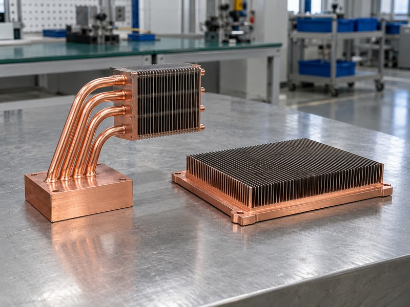
A flexible heat pipe is useful only when its routing or movement function solves a real integration problem. If the heat source and sink stay fixed, a supported formed assembly may avoid the cost and qualification work of cyclic-flex hardware. If heat needs spreading beneath a local fin field, a vapor chamber heat sink may fit the geometry better than a long routed pipe.
Can the mechanical layout remove the motion requirement?
Consider moving the heat sink with the source, placing a thermal connection closer to the pivot, or changing the package layout. A flexible solid conductor can be worth evaluating for a short path if its temperature drop, contact resistance, mass, and fatigue behavior are acceptable. A pumped liquid system is another architecture, but it adds flow connections and controls that require their own integration review.
- Identify whether transport distance or movement drives selection.
- Compare complete assemblies under the same boundary conditions.
- Include mass, service access, and qualification effort.
| Design need | Architecture to evaluate |
|---|---|
| Fixed remote sink | Factory-formed heat pipe assembly |
| Local spreading | Planar spreader or vapor chamber |
| Repeated relative motion | Qualified compliant thermal link |
Choose the architecture after checking whether a small mechanical change can remove the demanding movement condition from the thermal connection.
10. What should a flexible heat pipe RFQ include?
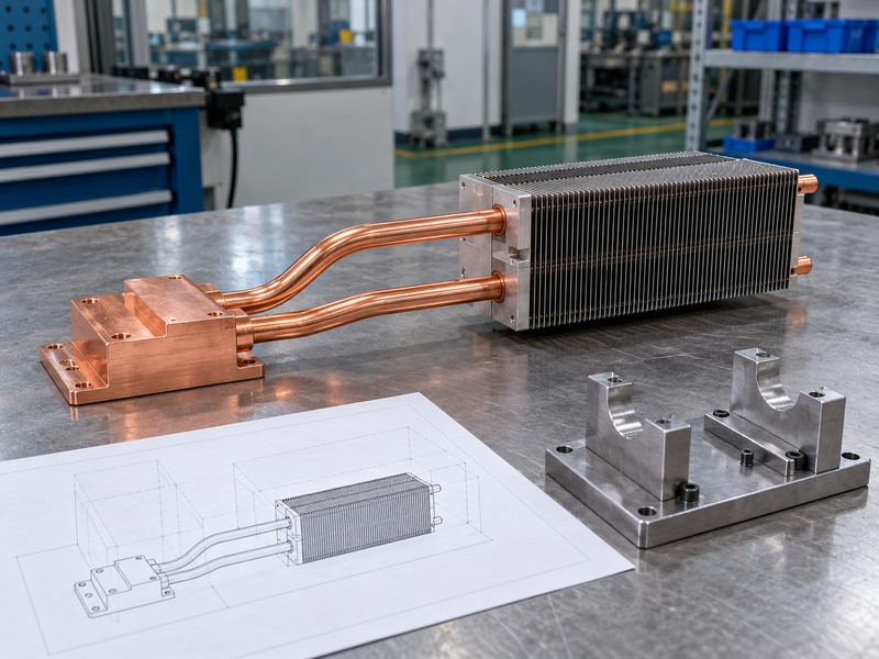
A flexible heat pipe RFQ should combine the heat-transfer specification with a mechanical movement specification. Supply the source map, temperature boundaries, installation attitudes, end-interface drawings, and every required position or travel path. Separate mandatory cyclic-flex qualification from a request for a stationary formed assembly, then ask the supplier to identify its proposed construction and the evidence available for that scope.
How do you make the quotation review useful?
Ask bidders to mark assumptions, unsupported duty conditions, development tasks, and the ownership of qualification testing. Confirm whether samples represent the intended production process and what changes trigger renewed approval. A quotation for standard formed copper-water pipes should clearly resolve fixed geometry and assembly interfaces before either team considers an additional movement requirement.
- Attach travel drawings or a defined motion model.
- Specify thermal and mechanical acceptance separately.
- Agree on forming, handling, and rework instructions.
| RFQ attachment | Defines |
|---|---|
| Thermal boundary | Required heat-transfer performance |
| Motion profile | Travel, timing, constraints, and life |
| Acceptance plan | Evidence needed before release |
Release the order when the construction, tested duty, and remaining qualification responsibilities describe the same assembly your equipment will use.
FAQ
Q1. Can I bend a standard heat pipe by hand?
Use only an approved procedure. Hand forming can create hidden deformation even when the tube looks acceptable afterward.
Q2. What’s the best minimum bend radius?
Use the selected supplier’s reviewed value for that construction, geometry, and forming process; a general diameter ratio is preliminary guidance.
Q3. Can a heat pipe follow a moving hinge?
Only a suitable, qualified assembly should do so. Define travel, constraints, temperature, and lifetime duty before selecting the device.
Q4. How do I know if forming damaged performance?
Compare matched thermal tests in the required orientation and load range, then investigate changes beyond the agreed measurement allowance.
Q5. Do thermal cycles prove bending life?
No. Thermal cycling and mechanical flexing apply different exposures; the qualification plan must cover the duty your equipment requires.
For a fixed formed Morton assembly review, send your geometry and thermal brief, and identify any movement requirement separately before the construction and validation scope are agreed.