
Use heat pipes when source-to-sink transport limits cooling, then compare complete assemblies under the equipment’s installed conditions. They suit equipment where the transport or spreading path limits cooling, including computing, telecom, power conversion, imaging, and industrial lighting. A larger fin stack cannot help much if heat never reaches it effectively. Evaluate heat pipe applications by mapping the source, transport path, interfaces, and final cooling boundary before selecting the assembly.
1. What problem should heat pipe applications solve?
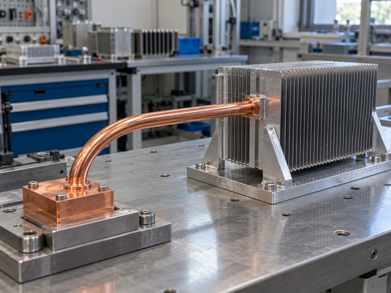
Useful heat pipe applications should solve a defined transport or spreading problem within a complete thermal path. A sealed working fluid evaporates near the source, carries energy as vapor, and condenses in a cooler region; a suitable return mechanism brings liquid back. The condenser still needs an air-cooled surface, liquid-cooled interface, or other effective sink, so a heat pipe cannot replace the final heat-rejection boundary.
How do you identify the limiting part of the path?
Measure or estimate the temperature drops between the device, contact block, transport section, fins, and cooling medium. As a hypothetical screening example, a 120 W source with an assumed allowable 30 K block-to-inlet rise has a 0.25 K/W total budget under steady conditions. If most of that budget is already consumed by poor airflow, improving transport alone may leave the equipment above its limit.
- Locate the hotspot and useful heat-rejection surface.
- Define temperature references and the steady heat load.
- Separate transport resistance from contact and rejection losses.
| Limiting region | First engineering question |
|---|---|
| Contact | Does the interface seat correctly? |
| Transport | Can heat reach the useful cooling area? |
| Rejection | Can air or coolant remove the load? |
Select a heat pipe when the path it improves accounts for enough of the temperature rise to justify the added assembly complexity.
2. How do servers and industrial computers use heat pipes?
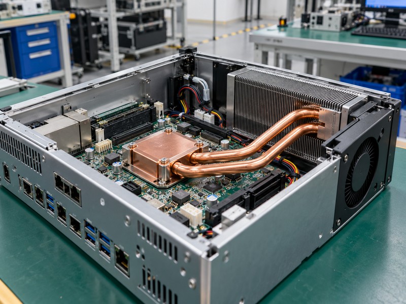
Servers and industrial computers use heat pipe applications to connect concentrated processor or accelerator heat to a larger fin region or an enclosure surface. Routing can help when connectors, memory, or height restrictions prevent placing the entire cooling surface directly above the source. The assembly must still match the device interface, available airflow, and mechanical keep-outs of the installed platform.
What changes between forced-air and fanless equipment?
A forced-air design needs fin passages that the installed fan can supply after duct, filter, and enclosure losses. A fanless design needs sufficient exposed surface and an installation attitude that supports natural convection, often with a longer path through the housing. Evaluate the local inlet temperature rather than room temperature, especially where upstream components or neighboring cards warm the air before it reaches the fins.
- Use the device manufacturer’s thermal and mounting requirements.
- Check simultaneous processor, memory, and power-stage loading.
- Include cables, covers, and production ducting in validation.
| Computing layout | Main review focus |
|---|---|
| Ducted server | Installed flow and air bypass |
| Compact industrial PC | Routing clearance and interface stack |
| Fanless computer | Housing rejection and mounting attitude |
Qualify the computing assembly in its populated chassis so the measured result includes the airflow obstructions and heat sources it will encounter.
3. Where do telecom platforms benefit from remote fins?
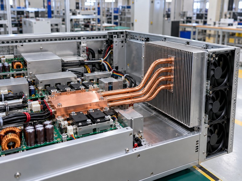
Telecom heat pipe applications can move losses from clustered devices toward a larger fin field or a better air channel. Power conversion stages, radio electronics, and control devices may occupy different heights and positions, making the source map as important as the total load. A remote condenser can help use available enclosure volume when a thick solid base would add mass or leave distant fins underused.
What should an outdoor or cabinet design account for?
Review the hottest inlet condition, solar heating where relevant, contamination, and the equipment’s installation attitudes. These conditions affect the complete cooling system even when the sealed heat pipe needs no external pump. Where the condenser sits below the evaporator, ask for construction-specific performance evidence instead of assuming that every wicked pipe retains the same capacity in every orientation.
- Define the actual operating and standby power map.
- Check air recirculation around cabinet inlets and outlets.
- Specify corrosion exposure and service-access constraints.
| Telecom constraint | Design response to evaluate |
|---|---|
| Offset heat sources | Routed transport to useful fin area |
| High local inlet temperature | Revised thermal budget |
| Multiple mounting attitudes | Orientation-specific validation |
Judge remote fins by the heat they receive and the air passing through them, rather than by their apparent surface area alone.
4. How can heat pipes support power electronics cooling?
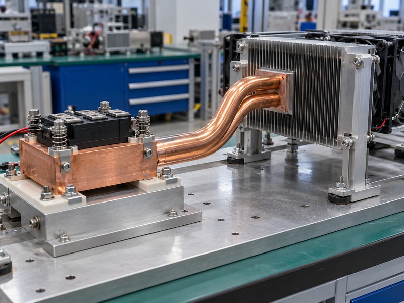
Power electronics heat pipe applications can distribute concentrated semiconductor losses into a broader air-cooled structure. The starting load is the device loss under the relevant electrical operating point, not the converter’s output power rating. Switching frequency, current, duty cycle, control mode, and neighboring losses can change the thermal map, so the electrical and thermal teams need the same operating assumptions.
What must be coordinated around the power module?
Review contact pressure, electrical isolation, creepage, grounding, and the mounting structure together. Heat sink mounting hardware should maintain the approved interface load without forcing the sealed pipes to carry structural loads. A heat pipe does not establish electrical isolation, and a low block temperature does not directly prove that every semiconductor junction stays within its allowed limit.
- Estimate losses for each required operating mode.
- Preserve the package manufacturer’s mounting constraints.
- Assess faults and derating with the equipment controls.
| Power-system input | Thermal implication |
|---|---|
| Device loss map | Local heat flux and source position |
| Isolation stack | Additional interface resistance |
| Fault duty | Required protection and transient review |
Approve the assembly against the electrical loss cases and interface stack that the equipment will use, including the required protection response.
5. Which imaging and machine vision layouts suit heat pipes?
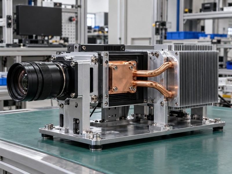
Imaging and machine vision heat pipe applications can route controller heat toward a remote fin region when space around optics, connectors, or precision structures is limited. They may also help reduce temperature gradients across a cooling base, depending on the layout. Define whether the requirement concerns a processor case, a sensor support, or an enclosure surface, because those temperatures serve different design purposes.
When does planar spreading fit better than routing?
If the source lies beneath a broad local fin field, a vapor chamber heat sink may suit the required two-dimensional spreading. If the cooling surface sits elsewhere, formed pipes may offer a more practical route around packaging obstacles. Neither choice proves optical stability: assess the equipment’s thermal expansion, mechanical supports, vibration, and calibration requirements through its own validation plan.
- Separate sensor, processor, and external-touch limits.
- Keep thermal loads away from sensitive mechanical references where feasible.
- Include steady operation and warmup behavior in system tests.
| Imaging requirement | Review question |
|---|---|
| Remote cooling surface | Can a supported pipe route reach it? |
| Local spreading | Would a planar spreader fit? |
| Precision alignment | How does the structure respond to heating? |
Choose the transport geometry from the package layout, then verify temperature and alignment with the imaging equipment operating as intended.
6. Can heat pipes cool a sealed enclosure?
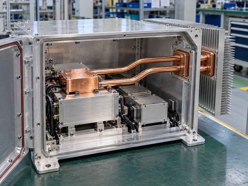
Sealed-enclosure heat pipe applications transfer heat toward the housing or through a designed heat-exchanger interface while preserving the enclosure’s required environmental barrier. Internal heat still has to reach the evaporator, and the exterior condenser must reject it to ambient. A passive thermal path can reduce reliance on exchanging dirty outside air with the electronics space, but its capacity depends on the full internal and external conditions.
What limits passive enclosure cooling?
The external surface needs a favorable temperature difference to reject heat, and solar load or hot ambient air can consume that margin. Inside the enclosure, distributed devices may need spreaders, contact interfaces, or internal air circulation to collect their losses. Define sealing, drainage, corrosion, and wall-penetration details separately from thermal performance; a heat-pipe concept alone does not establish an ingress-protection rating.
- Map heat from every significant internal component.
- Include the actual external airflow and installation location.
- Validate the environmental barrier after assembly.
| Enclosure region | Required check |
|---|---|
| Internal collection | Contact path or internal convection |
| Wall interface | Thermal connection and sealing |
| Exterior rejection | Ambient, solar load, and airflow |
Use a sealed thermal path only when its hottest ambient case leaves enough temperature difference for the exterior surface to reject the required load.
7. When are heat pipes useful in industrial LED lighting?
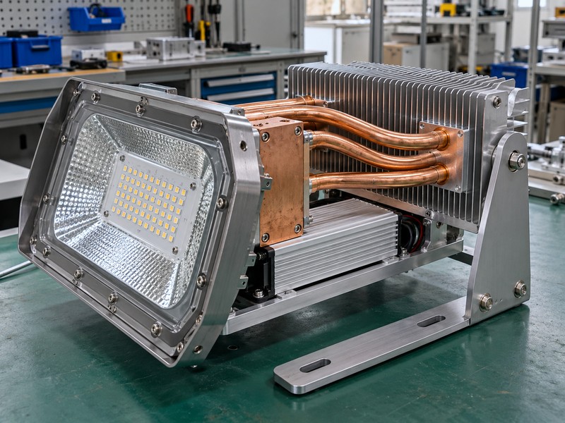
Industrial LED heat pipe applications can carry heat from a compact emitter region to a larger fin structure when the optical package restricts local cooling area. Begin with the LED module’s heat generation and junction-temperature requirements, plus the driver’s separate losses. Electrical input is not automatically equal to heat deposited at the LED contact base, so use suitable device data and a defined system boundary.
Which lighting constraints influence the thermal route?
Review fixture orientation, outdoor exposure, cleaning access, and the acceptable mass on the mounting structure. A fin arrangement that works in one attitude can lose natural-convection performance when the luminaire is tilted or enclosed. Keep the optical cavity, electrical isolation, and weather barrier in the mechanical review, and verify the chosen temperature reference with the module manufacturer’s instructions.
- Test every required installed attitude.
- Account for driver and emitter heating together.
- Define surface-temperature and service-access requirements.
| Lighting condition | Selection focus |
|---|---|
| Restricted optical package | Transport to available fin area |
| Passive outdoor fixture | Orientation and ambient exposure |
| Separate driver | Its own thermal path and interaction |
Add heat pipes when the remote surface offers useful rejection capacity that the local LED base cannot access efficiently through solid conduction.
8. How do heat pipes fit a hybrid liquid-cooled assembly?
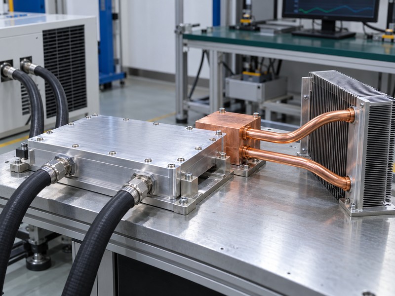
Hybrid heat pipe applications can cool auxiliary devices while a separate liquid cold plate handles a concentrated primary load. The sealed pipe transports heat internally without an external pump, whereas the cold plate connects to a pumped circuit with an inlet and outlet. Keeping those boundaries distinct makes thermal calculations, mechanical integration, and fault review easier to assess.
How should the two cooling paths be validated?
A hybrid liquid-cooled heat sink needs simultaneous loading of the main and auxiliary zones under their declared coolant and air conditions. Check whether warmed air or conduction through shared structures changes the auxiliary temperatures. Any backup cooling claim needs a stated reduced load, duration, and protection strategy; the presence of heat pipes does not automatically make full-power operation safe after coolant flow stops.
- Define coolant inlet temperature, flow, and allowable pressure drop.
- Specify auxiliary inlet air and installed airflow separately.
- Agree on reduced-flow and shutdown behavior with controls engineering.
| Path | Boundary to measure |
|---|---|
| Primary cold plate | Coolant inlet, flow, and pressure drop |
| Auxiliary heat pipe | Source temperature and air-side conditions |
| Shared assembly | Interaction during simultaneous loading |
Select the hybrid split from the complete heat map and validate both paths together before releasing normal and fault operating limits.
9. How do electronics uses differ from HVAC heat recovery?
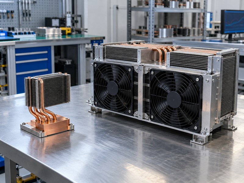
Electronics and HVAC heat pipe applications share phase-change transport but serve different thermal jobs. An electronics assembly commonly connects a small source to a fin field or housing, while an HVAC heat exchanger transfers energy between air streams or between sections around a cooling coil. A building energy-recovery result does not establish the capacity, orientation tolerance, or interface behavior of a compact electronics pipe.
Which assumptions should stay within their application?
Fluid choice, return mechanism, tube layout, and air-side design depend on the intended temperature range and installation. HVAC evaluation may include humidity, condensation, seasonal behavior, and exchanger pressure drop, while electronics evaluation often centers on source footprint, contact temperature, and package constraints. Compare evidence within the same application boundary before borrowing a performance claim or choosing an apparently similar copper-and-fin structure.
- Identify what receives heat and what rejects it.
- Check the fluid and return mechanism for the intended duty.
- Keep HVAC energy savings separate from electronic temperature limits.
| Application | Primary evaluation boundary |
|---|---|
| Electronics transport | Device contact to sink or inlet air |
| Air-stream recovery | Entering and leaving air conditions |
| Dehumidification arrangement | Cooling-coil and moisture behavior |
Use application-matched data so the shared heat-pipe principle does not hide different source conditions, acceptance criteria, and system responsibilities.
10. How should you qualify a new heat pipe application?
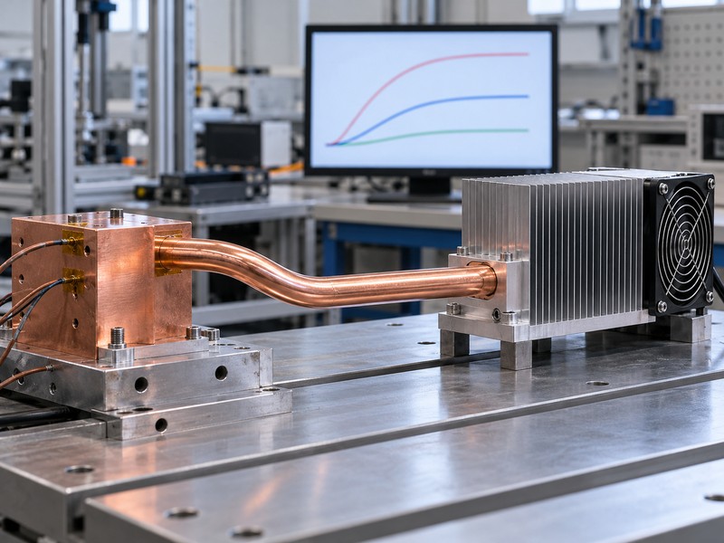
Qualify heat pipe applications by testing the proposed assembly against the equipment’s required thermal, mechanical, and environmental conditions. Start with a source map and temperature budget, then define geometry, interfaces, installation attitudes, and cooling boundaries. Record what the supplier will provide and what the equipment team must verify, particularly when a laboratory heater differs from the finished device.
What should your engineering brief contain?
Give the supplier a usable envelope, heat loads, source footprints, inlet conditions, interface details, and acceptance references. Add vibration, temperature exposure, service access, and production requirements where they affect the assembly. Preserve the tested drawing and BOM revision, then define which later changes require another thermal check or renewed qualification.
- Test relevant loads and the worst required orientation.
- Record sensor positions and measurement uncertainty.
- Keep fit, thermal, and environmental acceptance traceable.
| Approval input | Evidence to retain |
|---|---|
| Operating boundary | Heat, inlet conditions, and attitude |
| Assembly configuration | Drawing, BOM, interfaces, and supports |
| Acceptance result | Measurements and agreed limits |
Choose an assembly only after its validated conditions cover the equipment duty and the production specification preserves the tested thermal path.
FAQ
Q1. Can I use a heat pipe without a fan?
Yes, if the condenser’s passive cooling surface can reject the load under the required ambient and installation conditions.
Q2. What’s the best application for a heat pipe?
A useful starting point is a concentrated source separated from available cooling area, with transport resistance consuming the thermal budget.
Q3. Can a heat pipe cool below ambient temperature?
A passive heat pipe cannot provide refrigeration by itself; it needs a sink cool enough to receive the transported heat.
Q4. How do I know if liquid cooling is preferable?
Compare complete assemblies using the actual load, temperature budget, space, airflow, and available coolant boundary.
Q5. Does a heat pipe eliminate maintenance?
No. The equipment may still need fan, filter, interface, corrosion, and mounting checks even though the sealed pipe has no moving parts.
For a Morton application review, send your heat map and installation brief with source footprints, temperature limits, available airflow or coolant conditions, and the assembly space.