
Choose a loop heat pipe when the required routing, distance and operating conditions justify its added development and qualification effort. Its architecture can connect a concentrated heat source with a remote cooling boundary when a conventional pipe becomes difficult to integrate. For an industrial OEM, the challenge includes startup and low-load operation as well as full-power cooling. Define those conditions before deciding whether the additional loop development and qualification effort fits your equipment.
1. What makes a loop heat pipe a separate architecture?
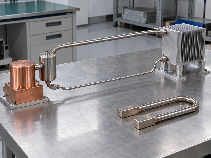
A loop heat pipe is a separate architecture because its evaporator provides capillary pumping while distinct transport lines carry vapor and returning liquid. A conventional wicked pipe normally carries vapor and liquid in opposite directions within one envelope. Bending that envelope into a U shape changes its routing, but does not create the evaporator, reservoir, and separate circulation paths of a capillary loop.
Which components identify the architecture?
Look for an evaporator containing the primary wick, a compensation chamber associated with that evaporator, a vapor line, a condenser, and a liquid return line. The loop remains sealed during normal use and does not rely on an external mechanical circulation pump. Some implementations use heaters or other controls for startup or temperature regulation. Specify those auxiliary functions separately from the fluid circulation mechanism.
- Identify each component on a system schematic.
- Separate transport lines from an external cooling circuit.
- Ask how startup and temperature control are implemented.
| Architecture | Fluid-return arrangement |
|---|---|
| Conventional wicked pipe | Wick along the common envelope |
| Capillary loop | Evaporator wick and separate liquid line |
| Pumped coolant circuit | Externally driven liquid flow |
Confirm the internal architecture before accepting a product name or an external loop-shaped outline as a sufficient specification.
2. How does the evaporator wick circulate the fluid?
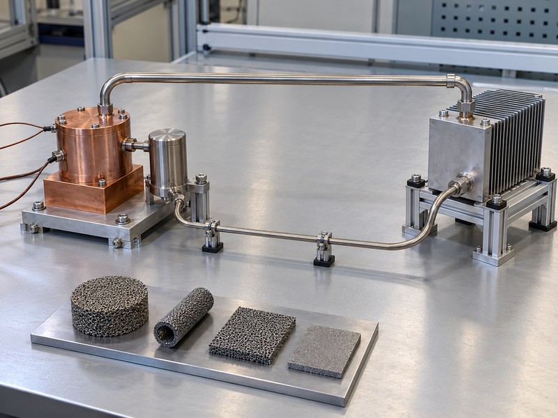
The primary wick in a loop heat pipe sustains a capillary pressure difference that supports circulation through the complete loop. Heat reaches working fluid at the evaporator and produces vapor, which flows toward the condenser. After releasing heat and condensing, liquid returns through its own line toward the evaporator. The available capillary pressure must cover pressure losses and any adverse body-force contribution.
Why does concentrating the wick help?
A conventional pipe can require returning liquid to travel through a wick over a substantial transport length. A loop architecture confines the principal capillary pumping structure to the evaporator, while its transport lines can be designed around their own flow requirements. Fine pores can provide high pumping pressure, but permeability and heat leakage also affect performance. Wick material and pore size must be selected within the complete evaporator design.
- Review capillary pressure and the full pressure-loss budget.
- Include wick permeability and material compatibility.
- Check the intended load, temperature, and orientation together.
| Design feature | Related constraint |
|---|---|
| Fine primary-wick pores | Available capillary pressure |
| Liquid and vapor passages | Flow pressure losses |
| Evaporator construction | Heat transfer and parasitic heat leak |
Evaluate the evaporator and transport circuit as one pressure-balanced system rather than selecting a wick by pore size alone.
3. What does the compensation chamber do?
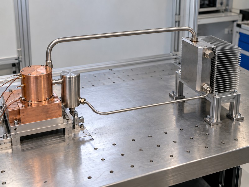
The compensation chamber in a loop heat pipe accommodates fluid inventory and participates in the thermal balance that determines operation. Its condition interacts with heat leaking from the evaporator, returning liquid temperature, and heat exchange with the surroundings. It is more than a spare storage volume. Changes in that balance can alter operating temperature and startup behavior even when source power remains unchanged.
Which thermal interactions need review?
Returning liquid may remove heat from the compensation chamber if it arrives below the local saturation temperature. Heat entering from the evaporator or surroundings can reduce that benefit. Insulation, mounting contact, and nearby warm hardware can change these paths. If temperature control is required, define whether compensation-chamber control is part of the proposed design and what power or control hardware it needs.
- Record the chamber’s mounting and ambient exposure.
- Define expected returning-liquid conditions.
- Identify intentional heating, cooling, or insulation.
| Interaction | Possible consequence |
|---|---|
| Evaporator heat leak | Raises the chamber thermal load |
| Returning liquid | Changes available cooling and inventory balance |
| Nearby equipment | Changes parasitic heat exchange |
Include the compensation chamber in the equipment thermal model and installation drawing instead of placing it wherever space remains.
4. Why do vapor and liquid use separate lines?
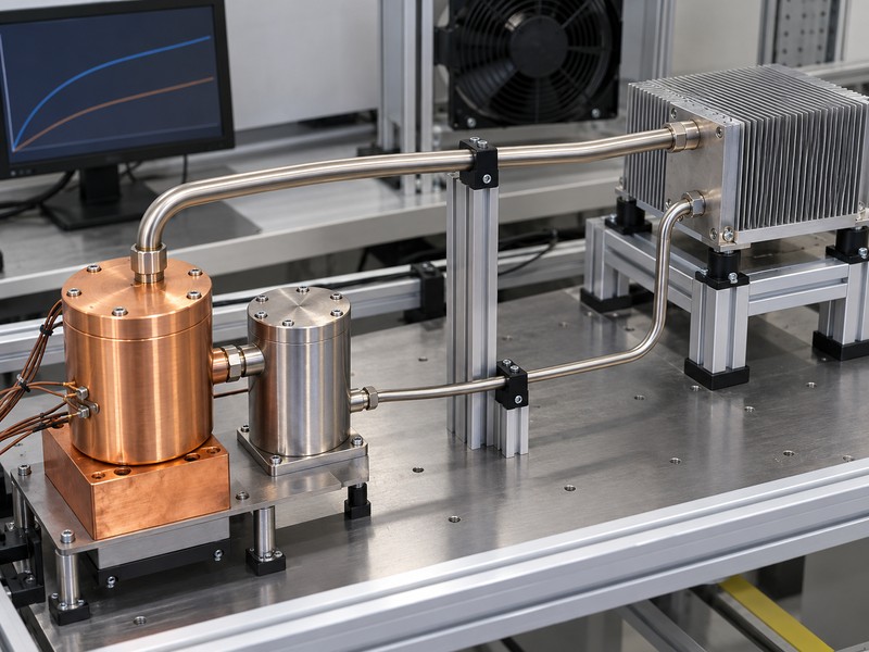
Separate lines let a loop heat pipe route vapor and liquid through passages designed for their respective flow conditions. This removes the conventional pipe’s counterflow arrangement from the transport section. It can help connect separated thermal regions, but line diameter, length, routing, heat exchange, and joining still require coordinated design. A clear external route does not establish an acceptable internal pressure budget.
How should you route the return line?
Show the liquid route alongside the vapor route and identify nearby heat sources. Heat gain along the return line can change the liquid condition entering the compensation chamber. Protect both lines from assembly loads, vibration, and accidental re-forming. Any requirement for flexible transport sections needs its own construction and movement qualification; ordinary metal tubing should not inherit a cyclic-flex capability from the word loop.
- Control line lengths and approved bend geometry.
- Identify hot surroundings along the return path.
- Provide supports without imposing unintended thermal loads.
| Routing item | Review question |
|---|---|
| Vapor line | Is pressure loss acceptable at required transport? |
| Liquid line | What heat gain occurs before return? |
| Supports and joints | Are mechanical and thermal effects controlled? |
Release the full line routing with the thermal design because installation changes can affect both pressure losses and fluid conditions.
5. How do distance and orientation affect performance?
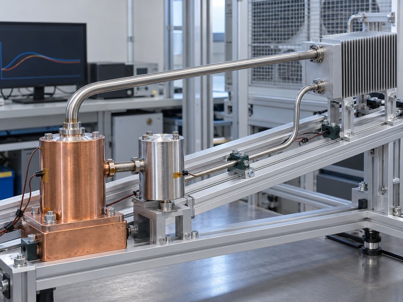
Distance and orientation affect a loop heat pipe through pressure losses, elevation effects, and fluid distribution, so neither has a universal allowable value. Separate lines and a capillary evaporator can support demanding transport layouts, but each design needs its own operating envelope. A long horizontal demonstration does not qualify an elevated evaporator at the same load. Ground operation and a low-gravity environment also impose different verification conditions.
What should an installation envelope include?
Specify source-to-condenser displacement in three dimensions, not only the length of tubing purchased. Identify allowed tilt, evaporator and chamber orientation, and the direction of gravity relative to both transport lines. Include the hot and cold environmental conditions that can influence startup. For a conventional heat pipe assembly used as a comparison, apply the same installation definition.
- Mark the least favorable evaporator elevation.
- Define permitted operating and storage positions separately.
- Request tests covering the actual routed configuration.
| Stated parameter | Additional definition needed |
|---|---|
| Transport distance | Line length and source-to-sink displacement |
| Orientation | Elevations, tilt, and component positions |
| Environmental range | Startup and sustained operating conditions |
Use tested combinations of distance, elevation, temperature, and load instead of combining independent maximum claims from separate demonstrations.
6. Why can startup fail at a low heat load?
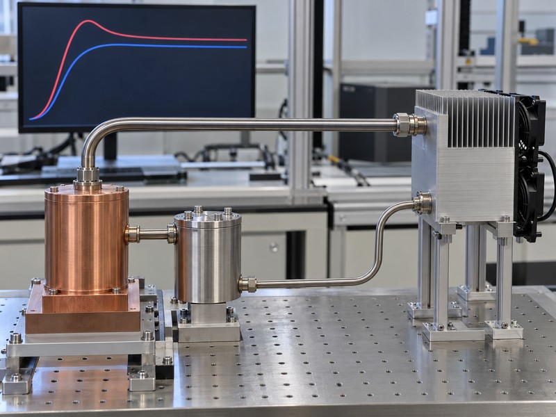
Startup can fail at a low heat load when a loop heat pipe cannot establish the required evaporation and circulation from its initial fluid distribution. Liquid-filled vapor grooves may need superheat before boiling begins. Heat leakage toward the compensation chamber can also raise its temperature and interfere with that process. Successful operation after a high-power start does not establish successful startup directly at the equipment’s minimum load.
Which startup conditions deserve separate tests?
Test after the specified shutdown, storage, and soak conditions, then apply the intended startup power sequence. Record evaporator, compensation-chamber, line, condenser, and source temperatures over time. A loop may start yet still exceed a component temperature limit before settling. If startup assistance is needed, include its controls, power, fault response, and acceptance criteria in the equipment design.
- Test direct startup at the minimum required heat input.
- Repeat starts from relevant warm and cold conditions.
- Define acceptable source peak, startup time, and stability.
| Startup result | Acceptance question |
|---|---|
| Circulation begins | Did startup occur consistently? |
| Transient temperature | Did every source remain within its limit? |
| Settled operation | Is low-load behavior stable enough? |
Require startup evidence that matches the equipment’s actual power sequence before using a steady-state result to justify the architecture.
7. What condenser boundary does the loop need?
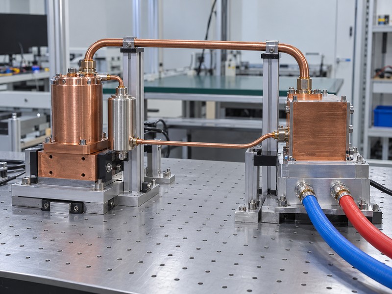
The condenser of a loop heat pipe needs a defined heat rejection boundary capable of removing the transported energy under the required conditions. It can couple to an air-cooled exchanger, a liquid-cooled block, or another suitable sink. The capillary loop transports heat to that boundary; the boundary determines where the energy goes next. A laboratory cold block can conceal limitations of the proposed installed heat exchanger.
What information makes a condenser comparison useful?
For air cooling, specify inlet temperature, installed airflow, duct arrangement, and bypass conditions. For liquid cooling, define coolant, inlet temperature, flow, pressure drop, and external loop limits. A tube-in-plate cold plate uses externally pumped coolant and has an inlet and outlet; it remains a separate circuit if used to cool a sealed loop’s condenser. Keep those circuits distinct in drawings and acceptance documents.
- Define contact area and attachment between condenser and sink.
- Include the warmest required cooling-medium condition.
- Examine heat exchanger and interface resistances together.
| Condenser coupling | Boundary data required |
|---|---|
| Air-cooled exchanger | Inlet air and installed airflow |
| Liquid-cooled block | Fluid, inlet temperature, and flow |
| Conductive sink | Contact conditions and sink temperature |
Test the loop with a representative condenser boundary so its accepted operating point remains relevant after installation.
8. When is a simpler cooling route a better fit?
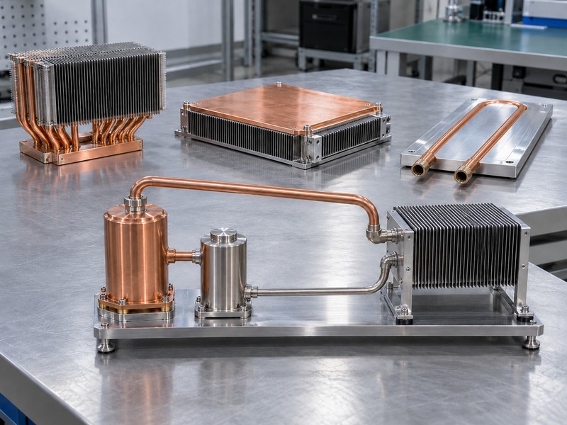
A simpler cooling route is often a better fit when a conventional pipe, spreading base, or cold plate can meet the requirement without the development scope of a loop heat pipe. Compare complete source-to-sink paths at matched operating conditions. A loop can justify its complexity when separated thermal regions, routing, and liquid-return requirements create a real architectural constraint. Its name alone provides no reason to select it.
Which alternatives should enter the comparison?
Review conventional pipes for a manageable routed connection and a vapor chamber heat sink for broad base spreading. If the equipment already has a compatible pumped coolant circuit, a cold plate may provide a direct and controllable rejection path. Compare space, startup requirements, service interfaces, production controls, and validation effort. Keep specialist loop development separate from any assumption about a supplier’s current product range.
- Identify the constraint that each architecture resolves.
- Compare assembly interfaces and verification cost.
- Check whether existing cooling infrastructure can serve the source.
| Requirement | Candidate to investigate |
|---|---|
| Short routed thermal path | Conventional heat pipe assembly |
| Wide source-to-base spreading | Vapor chamber |
| Available pumped coolant | Liquid cold plate |
Retain the loop candidate when its specific transport benefits solve a constraint the simpler alternatives cannot adequately address.
9. How should you qualify an installed loop?
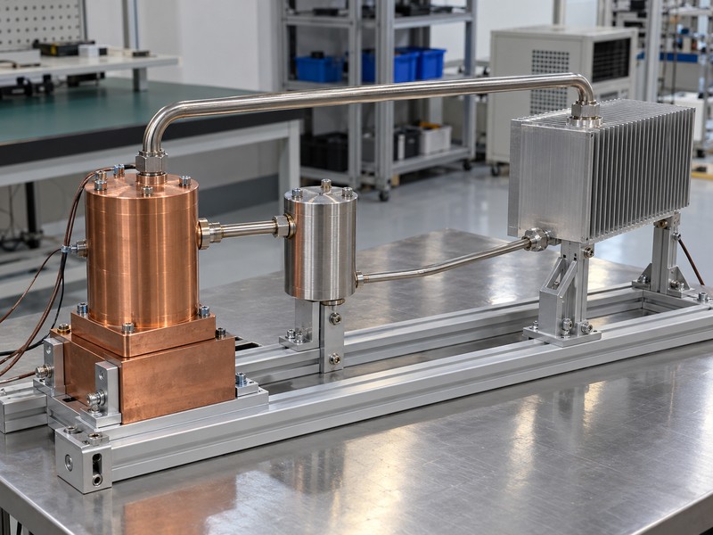
Qualify a loop heat pipe in its installed geometry with representative source power, mounting, condenser conditions, and operating sequences. Separate proof of basic circulation from proof that equipment temperature limits are met. Source contact resistance can change with flatness, interface thickness, and clamping conditions. Review mounting hardware with the thermal stack so repeat tests use the same controlled contact.
What belongs in the qualification matrix?
Include startup, minimum and maximum operating loads, load changes, warm and cold sink boundaries, and permitted orientations. Add environmental exposures from the equipment specification, followed by thermal checks that can detect damage or changed behavior. Define sample identification, sensor locations, stability criteria, and uncertainty. For long-life or specialist environments, qualification must address that actual service requirement rather than borrowing credibility from another industry’s use of the technology.
- Preserve time histories alongside settled temperatures.
- State allowable transient peaks and settling behavior.
- Control routing, materials, charge process, and approved changes.
| Qualification area | Evidence to retain |
|---|---|
| Thermal operation | Temperature and load histories |
| Installation | Drawing, orientation, and mounting records |
| Environmental exposure | Agreed exposure and post-test results |
Approve the identified design against the equipment requirement and review any later change that could alter the validated thermal path.
10. What belongs in a loop heat pipe review brief?
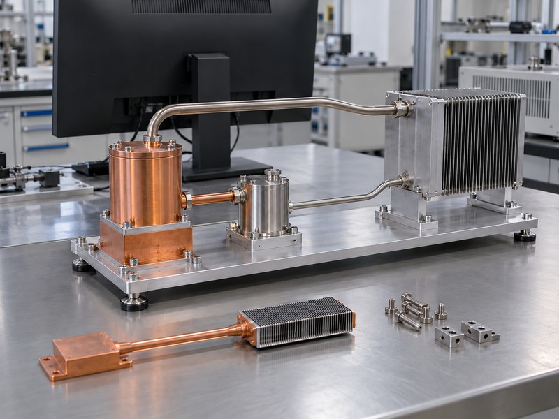
A loop heat pipe review brief should explain why the source-to-sink path is difficult and define the operating behavior the equipment requires. Include the heat map, minimum startup load, transient profile, allowable source temperature, and condenser conditions. Supply the full routing envelope and installation positions. An exploratory discussion should establish architecture feasibility and specialist responsibilities before it becomes a production quotation.
How can an OEM make the next review productive?
Separate fixed requirements from values that remain estimates. Ask for a proposed test envelope and identify assumptions that require prototype evidence. If you are also considering conventional heat sinks or liquid cold plates, provide the same thermal and mechanical inputs for those routes. A published product page or an article about loop operation does not establish a supplier’s ability to deliver qualified loop hardware.
- Provide source and condenser locations in one model.
- Include startup, steady load, transients, and environment.
- Define validation responsibilities and required records.
| Brief component | Specific content |
|---|---|
| Thermal duty | Power history and temperature limits |
| Integration | Routing, elevations, contacts, and supports |
| Development scope | Prototypes, tests, ownership, and review gates |
Request a feasibility response that identifies missing inputs and the evidence needed to support the proposed architecture.
FAQ
Q1. Can I make a loop heat pipe by bending a copper pipe?
No. A capillary loop requires its evaporator wick, compensation chamber, separate lines, and condenser to work as a coordinated system.
Q2. Does a loop heat pipe need a mechanical pump?
No external circulation pump is required for the capillary loop. Auxiliary heaters or controls may be part of a particular implementation.
Q3. What is the best transport distance for a loop?
Use the qualified design envelope. Distance, line geometry, elevation, fluid, temperature, and load determine the workable combination.
Q4. How do I know if low-load startup will work?
Request repeated startup tests at your minimum power after representative initial conditions, with source temperature and startup time recorded.
Q5. Can Morton supply a qualified loop system?
Confirm that scope directly. This article does not establish a Morton loop product offering or qualification for a specialist environment.
Send your source layout, routing constraints, startup profile, and condenser conditions when you discuss cooling options with Morton, and identify any loop-specific work that requires a specialist.