
Choose a transportation heat sink by matching heat loss, local cooling conditions and mechanical loads to your electronics’ temperature limits. A cooler that passes a bench test can still fail inside a parked vehicle with hot intake air. You need a defined thermal budget, a workable airflow path and mounting that survives the operating environment. This guide explains how to make those decisions before committing to tooling.
Start by treating your transportation heat sink as part of an assembly. A good extrusion cannot compensate for a thick interface pad, blocked exhaust or a loose clamp. Record the conditions around the component so a supplier can evaluate the same problem you are trying to solve.
1. What does a transportation heat sink cool?
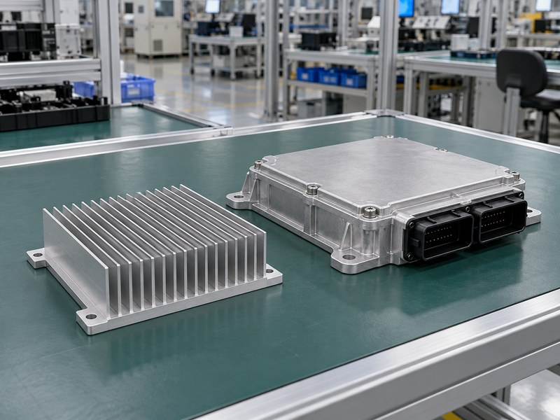
A transportation heat sink removes heat from equipment such as vehicle gateways, lighting drivers and power converters. The part normally conducts heat from a device into a larger metal surface exposed to air. Some assemblies also conduct heat into a chassis. Your specification should identify which path the design relies on, because an enclosure that traps warm air behaves differently from an open fin stack.
Which operating condition should define the design?
Start with the condition that produces the highest component temperature, which may occur while the vehicle is stationary. Road speed, fan operation, sunlight and neighboring electronics can change cooling conditions without changing your component’s power loss. A supplier needs that context before proposing a profile or quoting a thermal resistance. Describe both normal service and any short overload that the electronics must tolerate.
- Identify the device and its heat loss.
- Describe where heat leaves the enclosure.
- Record ambient temperature at the cooler’s inlet.
| Application | Useful design input |
|---|---|
| Vehicle gateway | Sealed enclosure and local air temperature |
| Lighting driver | Mounting orientation and operating duration |
| Power converter | Loss map across its duty cycle |
Use the duty cycle to decide which test condition deserves the most attention.
2. How do you size a transportation heat sink?
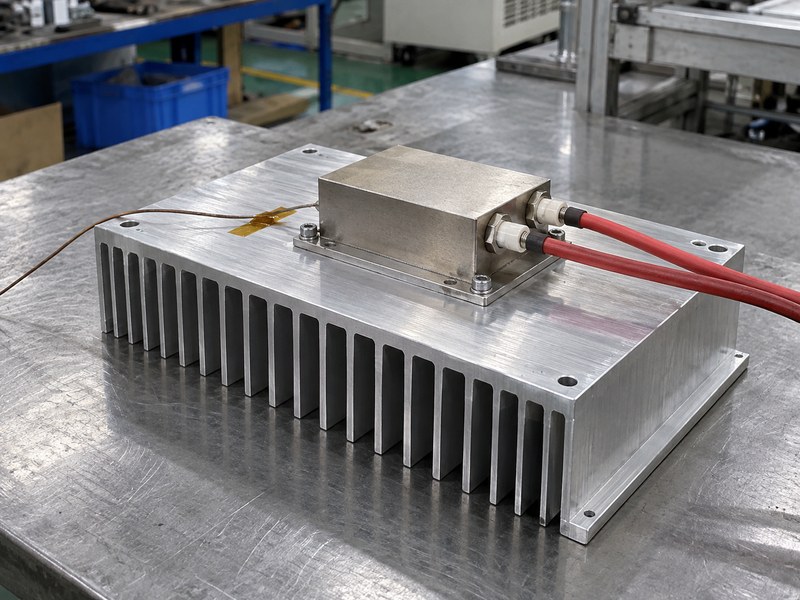
Size a transportation heat sink from the temperature rise available after accounting for the component and its interface. For a simple single-device steady-state path, the allowable sink-to-air resistance equals the temperature difference divided by heat loss, minus the other series resistances. Use the device manufacturer’s specified junction-to-case value only when its measurement conditions fit your assembly. Distributed sources need a spreading analysis as well.
What does a preliminary calculation tell you?
Consider an illustrative device dissipating 40 W with a 125°C junction limit and 60°C local air. The total available resistance is 1.625 K/W. If junction-to-case and interface resistance together consume 0.50 K/W, the sink-to-air allowance is 1.125 K/W before you reserve additional design margin. These assumed figures explain the calculation; they are not a cooler rating or a promise of vehicle performance.
- Use heat loss rather than electrical input power.
- Separate continuous operation from transient heating.
- Reserve margin for tolerances and aging.
| Budget item | Illustrative value |
|---|---|
| Temperature allowance | 65 K |
| Device heat loss | 40 W |
| Maximum sink-to-air resistance before margin | 1.125 K/W |
Request a resistance value measured under conditions that match your installation.
3. Which materials suit a transportation heat sink?
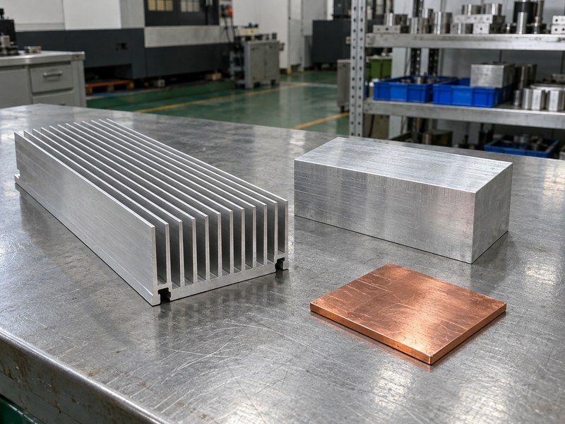
Aluminum often suits a transportation heat sink because it combines manageable weight with practical extrusion and machining options. Copper can help spread heat from a small source, but it adds mass and can change mounting loads. Compare the complete assembly instead of choosing solely from a conductivity table. Alloy, temper, surface condition and joining method all affect the result you receive.
When should you compare different manufacturing routes?
Use CNC machined heat sinks when contact faces, mounting features or a short prototype run need machining flexibility. For repeated straight sections, an extrusion may reduce machining effort. A copper insert needs a defined joint and a corrosion review wherever moisture can bridge dissimilar metals. Ask for material identification rather than accepting the word aluminum as a complete purchasing specification.
- Specify alloy and temper where they affect acceptance.
- Include total assembly mass in the comparison.
- Define which contact surfaces remain uncoated.
| Material option | Question for the supplier |
|---|---|
| Aluminum extrusion | Can the profile and base meet your tolerances? |
| Machined aluminum | Which features require additional setups? |
| Copper-assisted base | How is the insert joined and protected? |
Choose the construction that addresses your heat path without creating an unsupported joint.
4. How should fins follow the available airflow?
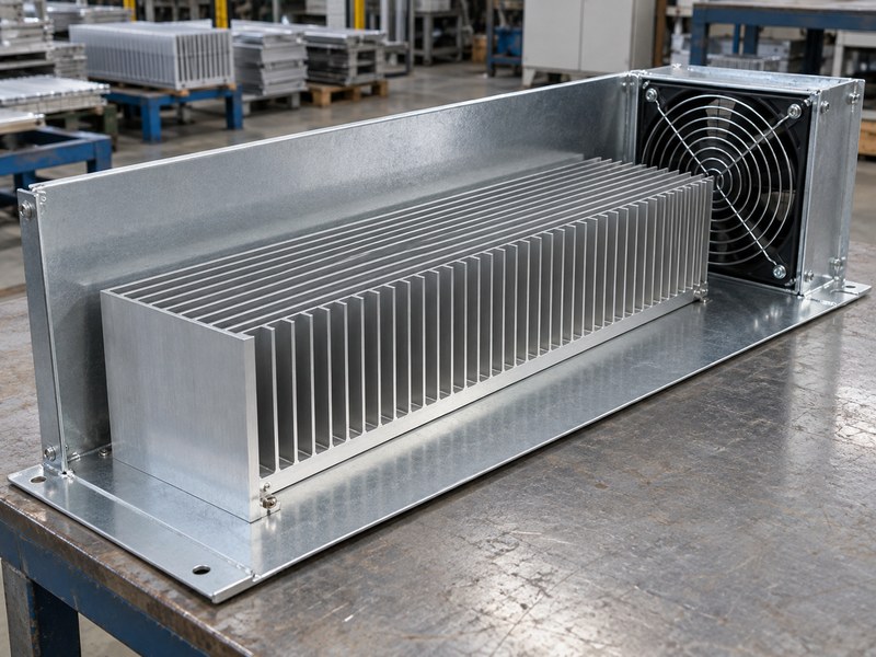
Align a transportation heat sink with the airflow that can pass through its channels in the installed position. Straight fins generally need an inlet and outlet along the channels. Tight fin spacing increases area but also adds flow resistance and can collect contamination. A larger fin count offers little benefit if most air bypasses the fins through a nearby gap.
What should you measure inside the enclosure?
Measure or estimate airflow through the cooler, rather than using the fan’s free-air rating. Filters, grilles, ducts and nearby components determine the operating point of the fan and system. Include the return path, because a restricted outlet can limit an otherwise generous inlet. If natural convection carries the heat, review gravity and fin orientation in each permitted mounting position before selecting a profile.
- Keep the inlet and outlet clear.
- Limit leakage around a forced-air fin stack.
- Allow access for cleaning where dust can collect.
| Observation | Possible consequence |
|---|---|
| Air bypasses the fins | Less useful flow through the cooler |
| Exhaust returns to the inlet | Higher local inlet temperature |
| Narrow channels collect debris | Rising resistance during service |
Test with the production grille and duct so the measured flow path remains relevant.
5. Can a transportation heat sink work without a fan?
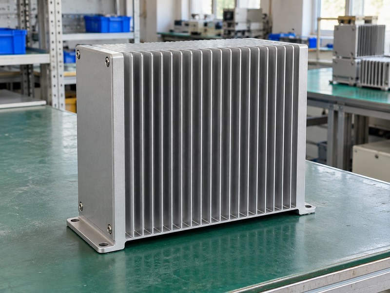
A transportation heat sink can work without a fan when natural convection, radiation and any chassis conduction keep temperatures within limits. That decision depends on heat loss, area, orientation and surroundings. A sealed enclosure can use external fins while protecting electronics inside, provided the internal components have a defined conductive path to the shell. Air moving outside the vehicle should not be your only cooling assumption.
What happens when space or heat loss changes?
A heat sink enclosure can combine packaging and cooling, but the enclosure wall must accept heat from the actual hot components. If a fan becomes necessary, account for its power, inlet contamination and failure response. A temperature-controlled fan can reduce operation at lighter loads. Validate the control thresholds and remaining temperature margin rather than assuming the controller will solve an undersized thermal design.
- Compare parked and moving operation.
- Check every approved mounting orientation.
- Define behavior after loss of forced airflow.
| Cooling approach | Condition to verify |
|---|---|
| Fanless external fins | Hot stationary operation |
| Forced-air fin stack | Installed airflow and blocked-flow response |
| Chassis conduction | Contact area and chassis temperature |
Select the approach from measured temperature limits and the service environment.
6. How does the interface change temperature rise?
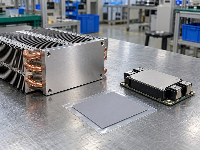
The interface adds resistance between the device and a transportation heat sink, so its thickness and contact pressure can change the final temperature. A flat mounting surface still has microscopic gaps. An interface material fills those gaps, but excess thickness lengthens the conduction path. A pad selected for a large tolerance gap may behave differently from a thin grease layer on closely controlled faces.
Which properties belong on the assembly drawing?
Specify compressed thickness, contact pressure and any electrical isolation requirement. A material’s bulk conductivity alone does not describe installed interface resistance. The device package may also limit allowable clamp force. Request interface performance data under a stated pressure and temperature, then verify the chosen assembly process can reproduce those conditions without bending the board or damaging the package.
- Measure the assembly’s gap range.
- Check electrical isolation requirements separately.
- Define pad location and clamp sequence.
| Interface detail | Reason to specify it |
|---|---|
| Compressed thickness | Defines the conduction distance |
| Contact pressure | Affects contact and material behavior |
| Isolation rating | Addresses the electrical requirement |
Confirm the interface after assembly instead of relying on the pad’s nominal thickness.
7. How do you mount a transportation heat sink?
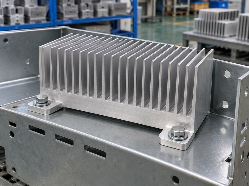
Mount a transportation heat sink through a load path that supports its mass without overloading the electronics. Vehicle vibration, shock and thermal expansion can change clamp pressure and stress solder joints. Tall or heavy coolers may need support from the enclosure. A fastener through a thin fin does not provide the same support as a defined boss or mounting ear on the base.
What should the fastening specification include?
Review heat sink mounting hardware alongside the device’s mechanical limits. Specify fastener engagement, tightening method and retention appropriate to the joint. If two materials expand differently, examine whether the joint can accommodate the movement. A spring clamp can help maintain force in some designs, but its travel and working load must match the actual tolerance stack.
- Support the cooler independently where necessary.
- Keep tool access clear of fins and wiring.
- Check retained clamp load after environmental tests.
| Joint feature | Acceptance question |
|---|---|
| Base mounting ear | Does it carry the required load? |
| Threaded connection | Is engagement defined in the drawing? |
| Spring element | Does its working range cover assembly variation? |
Inspect both mechanical security and thermal contact after the test sequence.
8. What changes in a dirty or wet installation?
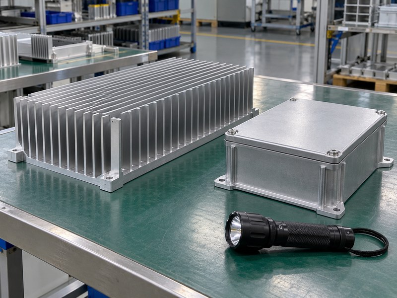
A transportation heat sink installed near dust, road spray or condensation needs a review of fouling, corrosion and drainage. Surface treatment can protect exposed aluminum, but a coating can also affect contact faces and electrical bonding. Specify where the finish applies. Do not treat a decorative finish as evidence that the complete enclosure meets an ingress or corrosion requirement.
How do you avoid maintenance surprises?
Use the real contamination environment to decide whether filters, larger passages or external fins make sense. Filters require access and a replacement plan. Fins exposed to road debris may need protection that itself restricts airflow. Review the complete installed arrangement, including connector seals and drain paths, because water retained beside a joint can create a different corrosion risk from a brief surface splash.
- Define cleaning access and permitted methods.
- Identify dissimilar-metal contact points.
- Mask thermal or bonding faces where required.
| Exposure | Design review |
|---|---|
| Dust | Passage width, filters and cleaning access |
| Condensation | Drainage and contact protection |
| Road spray | Seals, coating coverage and installation position |
Choose environmental tests from the vehicle’s requirements rather than from a generic product description.
9. How should you validate the finished assembly?
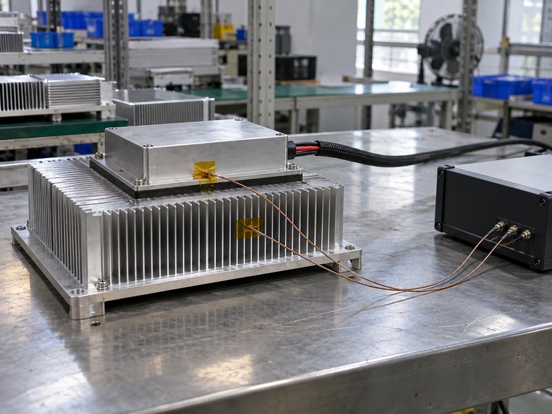
Validate a transportation heat sink by measuring the assembled equipment at defined loads and environmental conditions. Record the device temperature using package-specific thermal measurement guidance, together with local inlet air and heat loss. A surface temperature on a shiny fin does not establish junction temperature. Sensor placement, mounting and emissivity assumptions can introduce errors large enough to change your decision.
Which comparisons make a test useful?
Compare prototypes under the same interface, orientation and airflow. If the design uses thermal pads, retain their identity and compressed condition in the test record. Repeat the thermal check after the relevant mechanical and environmental sequence. That reveals changes such as joint movement or interface degradation that an initial temperature measurement would miss.
- Document heater or device power independently.
- Record sensor positions and uncertainty.
- Compare before-test and after-test temperatures.
| Test record | What it lets you compare |
|---|---|
| Inlet air temperature | Available temperature rise |
| Device loss | Applied thermal load |
| Assembly and interface details | Repeatability between samples |
Ask for the test setup with the result so you can judge whether it represents your installation.
10. What should you send with a supplier RFQ?
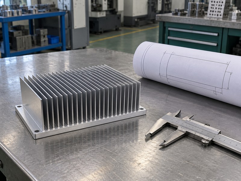
Send a transportation heat sink RFQ with a drawing, heat-loss range, temperature limits and installation constraints. Include quantity, inspection requirements and the interfaces that the supplier must preserve. A request based only on overall dimensions leaves the supplier guessing about contact faces, allowable mass and cooling conditions. Mark uncertain inputs so the quotation can separate confirmed requirements from assumptions that still need testing.
Which decisions should be settled before tooling?
Agree on the mounting arrangement, material and prototype acceptance test before releasing production tooling. Specify which features will be machined after forming and how the supplier will inspect them. Discuss packaging if thin fins or flat contact faces could be damaged during shipment. Keep the prototype revision and accepted test configuration tied to the production drawing so later changes receive a thermal review.
- Provide mechanical files and a thermal brief.
- Define inspection points and sample acceptance.
- State what still needs engineering confirmation.
| RFQ attachment | Useful content |
|---|---|
| Mechanical drawing | Datums, contact faces and tolerances |
| Thermal brief | Loss, ambient conditions and temperature limits |
| Validation plan | Test setup and acceptance criteria |
Send your drawing and operating conditions when you contact us. A defined heat path and a repeatable test give both teams a practical basis for selecting the next prototype.
Frequently asked questions
Q1: Can I use a standard extrusion in a vehicle?
Yes, if its thermal performance, mounting and environmental behavior meet your assembly’s requirements. A standard profile still needs validation in the installed position.
Q2: What’s the best material for a lightweight cooler?
Aluminum is often a practical starting point. Compare the required base thickness, fin geometry and total assembly mass before choosing an alloy or process.
Q3: How do I know if a fan is necessary?
Test the available passive cooling path at the required load and ambient temperature. Add forced airflow when the validated passive arrangement cannot meet your limits.
Q4: Can I select a cooler from one thermal resistance number?
Only when its stated test conditions represent your installation. Orientation, airflow, source footprint and interface can change the installed result.
Q5: Should I repeat thermal tests after vibration testing?
Yes, when vibration forms part of your validation plan. Compare temperatures and inspect the mounting joint to identify changes in contact or clamp force.