
Choose a transportation radiator heat sink by defining whether your equipment needs direct air cooling or a liquid loop with a separate heat exchanger. Those arrangements require different interfaces, calculations and tests. A radiator specified only by its outer dimensions can fit the vehicle while failing to reject the required heat at low speed. Start with the complete path from the device to ambient air before comparing components.
A purchasing brief for a transportation radiator heat sink should identify each component’s function. Use consistent names for the cold plate, pump and radiator. That gives your thermal engineer, mechanical designer and supplier the same system boundary when they discuss performance or responsibility.
1. What is a transportation radiator heat sink?
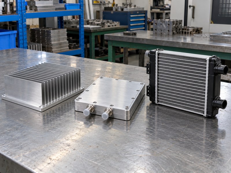
A transportation radiator heat sink is a purchasing phrase that can describe different cooling components, so define the intended construction in your drawing. A finned heat sink conducts heat from a device into surfaces exposed to air. A liquid cold plate transfers device heat into coolant. A radiator transfers heat from that coolant into air elsewhere in the loop. Each part handles a different stage of the same energy path.
Which words prevent specification errors?
Write the function beside the part name. A supplier may use radiator for an extruded finned product, while a vehicle cooling engineer expects tubes, fins and coolant connections. Neither vocabulary settles the design requirement. A marked interface drawing does: show where heat enters, where it leaves, and which team supplies each connection. Confirm whether quoted performance covers one component or the full installed assembly.
- Identify the source-side component.
- Identify the final heat-rejection component.
- State whether coolant flows through the quoted part.
| Component | Heat-transfer role |
|---|---|
| Finned heat sink | Device to air |
| Liquid cold plate | Device to coolant |
| Coolant radiator | Coolant to air |
Use these functional descriptions wherever a translated product name could cause ambiguity.
2. How do you define the complete cooling path?
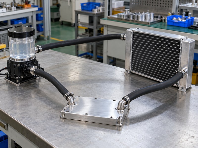
Define a transportation radiator heat sink system by tracing heat from the source through every interface to its final sink. In a liquid loop, include the device contact, cold plate, coolant, radiator and surrounding air. Also include pump heat where it affects the loop’s energy balance. A cold plate can maintain a low device-to-coolant resistance while the radiator still lacks enough air-side capacity.
Where should the system boundary sit?
Set responsibilities at measurable interfaces. For example, specify coolant inlet temperature and flow at the cold plate, then specify ambient inlet air and airflow for the radiator. If those conditions depend on another supplier’s component, document the dependency. A quotation for the cold plate alone cannot establish the inlet coolant temperature that the rest of the vehicle must provide.
- Draw the flow order and interface locations.
- Assign responsibility for inlet conditions.
- Include hoses, fittings and controls in the boundary review.
| Interface | Requirement to define |
|---|---|
| Device to cold plate | Contact geometry and allowable temperature |
| Cold plate inlet | Coolant temperature, flow and fluid |
| Radiator air inlet | Local air temperature and available flow |
Check these boundaries before comparing two suppliers’ performance claims.
3. How do you calculate coolant heat transport?
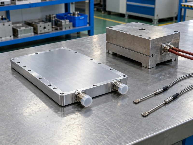
Calculate coolant heat transport for a transportation radiator heat sink from mass flow, specific heat and temperature rise. Under steady conditions, Q equals mass flow multiplied by specific heat and coolant temperature rise. Use fluid properties at the relevant concentration and temperature. The calculation describes transported heat; it does not determine junction temperature or prove the radiator can reject that heat to the available air.
What can an illustrative calculation establish?
Assume water carries 1,000 W with an allowed rise of 5 K and a specific heat of approximately 4,180 J/kg·K; check water property data at your operating temperature. The required mass flow is about 0.048 kg/s, or roughly 2.9 L/min using an approximate density of 1 kg/L. This is a calculation example, not a recommended vehicle coolant or a guaranteed operating point. A glycol mixture requires its own property values and compatibility review.
- State the fluid and concentration.
- Distinguish mass flow from volumetric flow.
- Check the component’s permitted coolant temperature.
| Illustrative input | Value |
|---|---|
| Heat carried | 1,000 W |
| Allowed fluid rise | 5 K |
| Approximate water flow | 2.9 L/min |
Use the result as an input to hydraulic and radiator sizing, then verify the assembled loop.
4. What limits a transportation radiator heat sink in traffic?
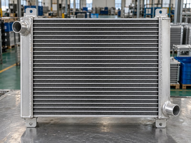
At low vehicle speed, a transportation radiator heat sink may be limited by air-side flow and the temperature difference between coolant and inlet air. Ram air available on the road can disappear at a stop. A radiator placed behind another hot heat exchanger may also receive warmer air than the weather report suggests. Specify local inlet conditions instead of assuming outside ambient reaches the core unchanged.
How should you compare radiator cores?
Compare heat rejection with the same fluid, flow, inlet temperatures and air conditions. Core thickness and fin density affect both area and pressure drop. A denser core may need more fan pressure and can behave poorly if the shroud leaks. Review the gap around the core and the outlet path so air cannot take a lower-resistance route around the fins.
- Include stationary operation in the thermal case.
- Review fan and shroud performance together.
- Check fouling and access for cleaning.
| Installation detail | Possible effect |
|---|---|
| Upstream hot exchanger | Higher radiator inlet air temperature |
| Shroud leakage | Less airflow through the core |
| Blocked exhaust path | Reduced installed fan flow |
Ask for a performance map that covers your low-speed operating conditions.
5. How do pumps and pressure drop affect selection?
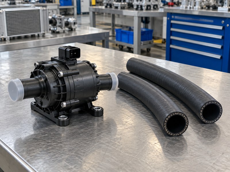
Select the pump for a transportation radiator heat sink from the intersection of its pump curve and the loop’s resistance curve. The pump’s unrestricted flow rating does not establish installed flow. Cold-plate passages, radiator tubes, hoses, valves and fittings each contribute resistance. Fluid viscosity changes with temperature, so cold startup can produce a different operating point from a warmed-up test.
When should you compare cold-plate constructions?
A microchannel cold plate can provide a compact heat-transfer surface, but its pressure drop and cleanliness requirements need review. Compare it with other channel arrangements using the same coolant and flow conditions. Check pump inlet conditions and the manufacturer’s requirements for filling and air removal. Increasing pump speed without reviewing the complete circuit can add power and noise without resolving the actual bottleneck.
- Obtain pressure-drop curves for the components.
- Include fittings and hose lengths in the model.
- Check filling, bleeding and low-temperature operation.
| Hydraulic input | Reason to include it |
|---|---|
| Component pressure drop | Sets part of the loop resistance |
| Fluid viscosity | Changes resistance with temperature |
| Pump performance curve | Predicts installed flow with the system curve |
Measure flow in the assembled loop before accepting the thermal result.
6. Which materials and coolant belong together?
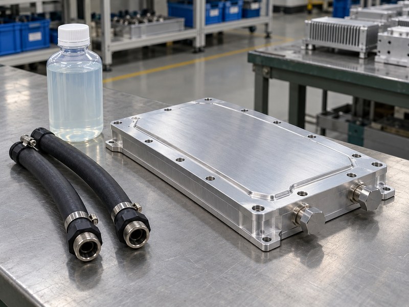
Materials in a transportation radiator heat sink loop must be compatible with the specified coolant and operating conditions. Include cold plates, radiator tubes, pumps, hoses, seals and fittings in that review. Water quality, additives, concentration and service intervals can affect corrosion and deposits. A material that works in one controlled loop may behave differently when mixed metals or an unsuitable fluid enter the circuit.
What should the purchasing specification control?
For an aluminum assembly, document the fluid specification and approved wetted materials. Review seal compatibility across the full temperature range. A vacuum brazed cold plate also needs a defined cleanliness and leak-test requirement. External anodizing does not establish the condition of internal fluid passages, and a coating description alone does not settle compatibility.
- Identify all wetted metals and elastomers.
- Define coolant concentration and water quality.
- Specify maintenance and contamination limits.
| Item | Information to request |
|---|---|
| Cold plate | Wetted alloy and joining process |
| Seal | Material and fluid compatibility |
| Coolant | Concentration, additives and service guidance |
Review substitutions before purchase so a fitting or seal change receives the same compatibility check.
7. What happens when flow or airflow fails?
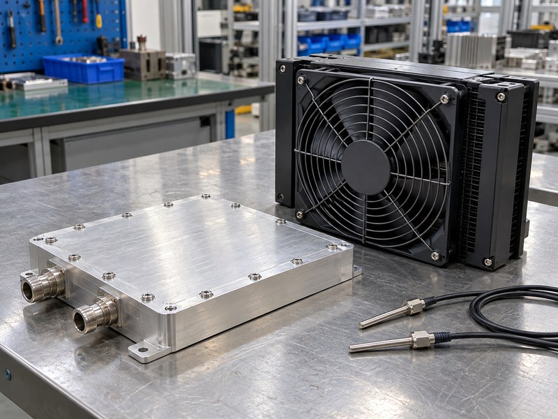
A transportation radiator heat sink needs a defined response when a pump stops, a fan fails or a passage becomes restricted. The amount of time available depends on heat input and the assembly’s thermal capacity. A large metal mass may delay temperature rise, but it cannot reject continuous heat without a working path to the environment. Define the required derating or shutdown behavior from component limits.
Which sensors support that response?
Select sensors according to the failure you must detect. A coolant temperature sensor may respond differently from a device temperature estimate or a flow switch. Decide where each measurement belongs and how the controller handles a missing or implausible signal. Keep alarm thresholds tied to a validated operating envelope rather than borrowing a temperature from an unrelated cooling product.
- Define pump-loss and fan-loss cases separately.
- Check sensor location and response time.
- Verify the controller’s derating or shutdown action.
| Fault | Validation question |
|---|---|
| Pump stops | Does device protection act before its limit? |
| Radiator airflow falls | Can control reduce heat generation? |
| Sensor signal fails | Does the controller enter a defined state? |
Test the protection behavior with controlled fault conditions and appropriate equipment safeguards.
8. Which manufacturing details affect reliability?
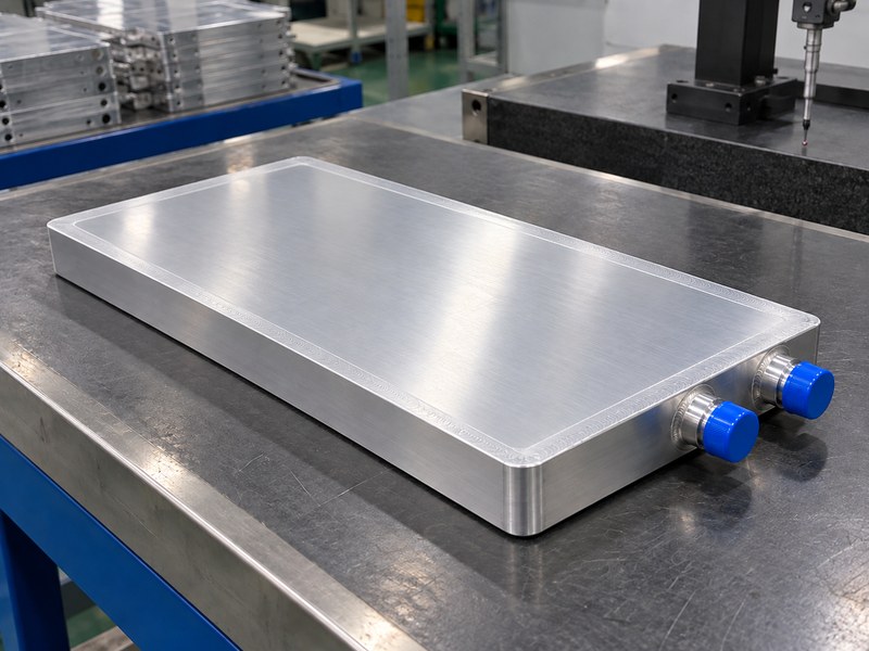
Manufacturing details affect a transportation radiator heat sink through contact quality, joint integrity and mechanical support. Flatness matters where a power module contacts a cold plate. Port location and hose routing affect packaging loads. A sealed passage also needs an inspection method suited to the joint and the assembly’s service requirements. Define these features on the drawing so acceptance does not depend on appearance alone.
What should you inspect on a cold plate?
For a friction stir welded cold plate, agree on the joining and inspection requirements with the supplier. Measure the finished contact surface after the operations that can alter it. Provide brackets or strain relief where hose loads could stress a port. A successful leak check addresses fluid containment under its stated conditions; it does not replace thermal or fatigue validation.
- Identify functional datums and contact faces.
- Define port geometry and fitting engagement.
- Separate leak, dimensional and thermal acceptance.
| Feature | Inspection focus |
|---|---|
| Device contact surface | Flatness and surface condition |
| Coolant port | Position, thread and sealing interface |
| Joined cover | Specified integrity and leak acceptance |
Tie the inspected configuration to the drawing revision supplied for vehicle testing.
9. How do you test the complete installed loop?
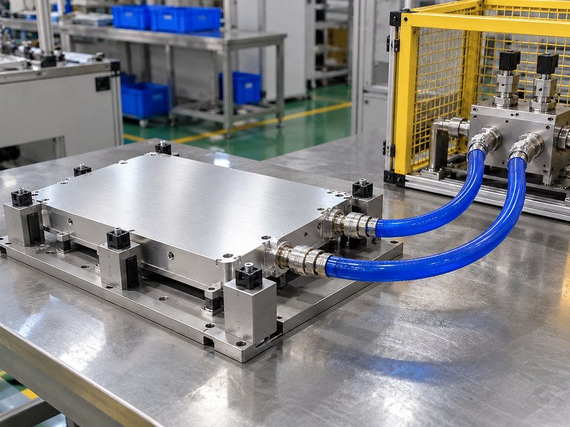
Test a transportation radiator heat sink loop with the intended fluid, controlled heat input and representative installation restrictions. Record coolant inlet and outlet temperatures, flow and local air conditions after reaching a defined steady condition. Track the device temperature separately. A small coolant temperature rise can indicate high flow, low heat input or a measurement problem; it does not by itself establish good cooling.
What should the test report allow you to reproduce?
Record the fan setting, pump setting, hose arrangement, sensors and device interface. Include measurement uncertainty when comparing a small temperature difference. If you calculate heat from fluid measurements, compare it with an independent estimate of supplied heat and explain relevant losses. Perform pressure and leak tests with a controlled procedure suitable for the rated assembly, then repeat the required checks after environmental exposure.
- Keep the fill and bleed procedure consistent.
- Document the definition of steady operation.
- Retain raw conditions with the reported result.
| Measurement | Purpose |
|---|---|
| Fluid flow and temperature rise | Estimates transported heat |
| Device temperature | Checks the component limit |
| Local inlet air | Establishes radiator operating conditions |
Reject comparisons that use different inlet conditions without explaining the difference.
10. What belongs in your cooling-system RFQ?
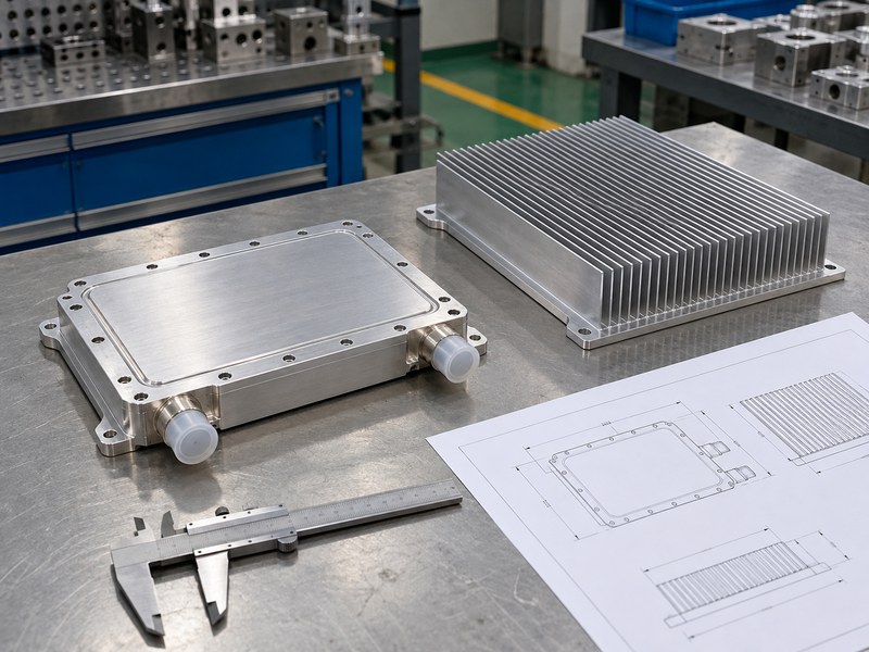
A transportation radiator heat sink RFQ should state the function, scope of supply and acceptance conditions for each component. Include the required heat load, operating temperatures, coolant, allowable pressure drop and packaging envelope. Mark whether the supplier provides the cold plate alone or a complete assembly. That distinction changes both the quotation and the performance evidence you should request.
How do you avoid comparing incompatible quotations?
Ask each supplier to use the same inlet conditions and explain any assumptions. Request separate information for thermal performance, pressure containment and mechanical interfaces. Include quantities, drawing revisions, inspection records and prototype timing. If a requirement is still uncertain, identify the test that will settle it before either team releases production tooling or substitutes a different construction.
- Provide the system diagram and interface drawing.
- Define fluid and air conditions for performance claims.
- List required prototype and production records.
| RFQ section | Decision it supports |
|---|---|
| Scope and interfaces | Establishes supplier responsibility |
| Operating envelope | Makes performance claims comparable |
| Acceptance plan | Defines how the prototype will be evaluated |
Send your thermal brief and drawings when you contact us. State which cooling component you need and which inlet conditions your vehicle can provide so the prototype review starts with a testable requirement.
Frequently asked questions
Q1: Can I replace a vehicle radiator with a finned heat sink?
Only if a complete thermal assessment supports that change. A radiator normally serves a coolant loop, while a direct-air heat sink needs a suitable path from the heat source.
Q2: What’s the best coolant flow rate for my cold plate?
There is no universal rate. Use heat load, fluid properties, allowable temperature rise and the cold plate’s pressure-drop curve to define the operating range.
Q3: How do I know if the radiator is the bottleneck?
Measure the complete loop under controlled conditions. Compare device, coolant and local inlet air temperatures together with flow and radiator airflow.
Q4: Can I use the same fluid with aluminum and copper parts?
Only after reviewing the complete wetted-material list and coolant guidance. Mixed-metal systems need appropriate corrosion control and maintenance.
Q5: Does a leak test prove that the assembly cools adequately?
No. A leak test evaluates containment under its stated conditions. Thermal performance needs a separate test at the specified heat load and inlet conditions.