
Choose aluminum heat sink tolerances from the contact surface, mounting arrangement, airflow geometry, and enclosure fit. A request for a shape accuracy radiator aluminum heat sink can still leave those requirements undefined. Your sample may fit while a later batch rocks against the device or binds inside the housing. Put measurable limits on the functional features, then agree how the finished parts will be inspected.
1. What does shape accuracy radiator aluminum heat sink mean?
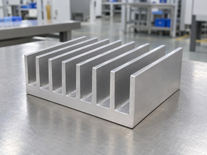
The phrase describes a heat sink whose finished geometry must satisfy agreed drawing limits. For a shape accuracy radiator aluminum heat sink, those limits can cover the mounting face, outside envelope, fin arrangement, and hole locations. The phrase alone does not define an alloy, a manufacturing method, or an accuracy class. A supplier needs a drawing and acceptance criteria before making a meaningful capability commitment.
Which surfaces perform a function?
Start with the assembled product and identify the surfaces that transfer heat, locate hardware, or maintain a clearance. A mounting face can need a different control from an exposed fin tip. Fin geometry also affects airflow, so dimensional acceptance should follow the thermal design rather than appearance alone.
- Mark the device contact footprint and the assembly locating features.
- Separate functional limits from cosmetic requirements.
- Identify the finished condition in which each requirement applies.
| Feature group | Possible requirement | Functional reason |
|---|---|---|
| Device interface | Flatness and surface texture | Consistent contact |
| Mounting features | Location and orientation | Assembly alignment |
| Fin bank | Height, spacing, and envelope | Airflow and clearance |
A purchase description becomes inspectable when each requirement points to a feature, a limit, and an evaluation method.
2. Which dimensions need the tightest tolerances?
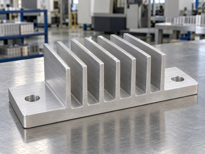
Apply the tightest tolerances where variation can prevent assembly or exceed a thermal or electrical limit. A shape accuracy radiator aluminum heat sink drawing rarely benefits from one narrow tolerance applied indiscriminately. A screw pattern may need close location control while a noncontact outside edge can vary more. Ask what fails when each dimension moves toward its limit before paying for tighter production control.
How can you rank features for review?
Evaluate the heat-source interface, locating surfaces, fastener access, and airflow passages as separate functions. For an enclosure-guided assembly, width and straightness can interact across the full insertion length. A short sample that slides into a housing does not establish the fit of a much longer production part.
- Trace each close tolerance to an assembly or performance requirement.
- Check feature interactions at their permitted limits.
- Identify dimensions that can remain under a general drawing tolerance.
| Review priority | Example feature | Question to resolve |
|---|---|---|
| Contact | Device mounting region | Can the interface accommodate variation? |
| Location | Fastener or guide feature | Will mating parts still align? |
| Clearance | Fin tips and housing walls | Is the gap sufficient at the limits? |
Discuss the difficult features with the supplier before freezing the drawing, including which ones require machining or dedicated inspection.
3. How do size, flatness, and parallelism differ?
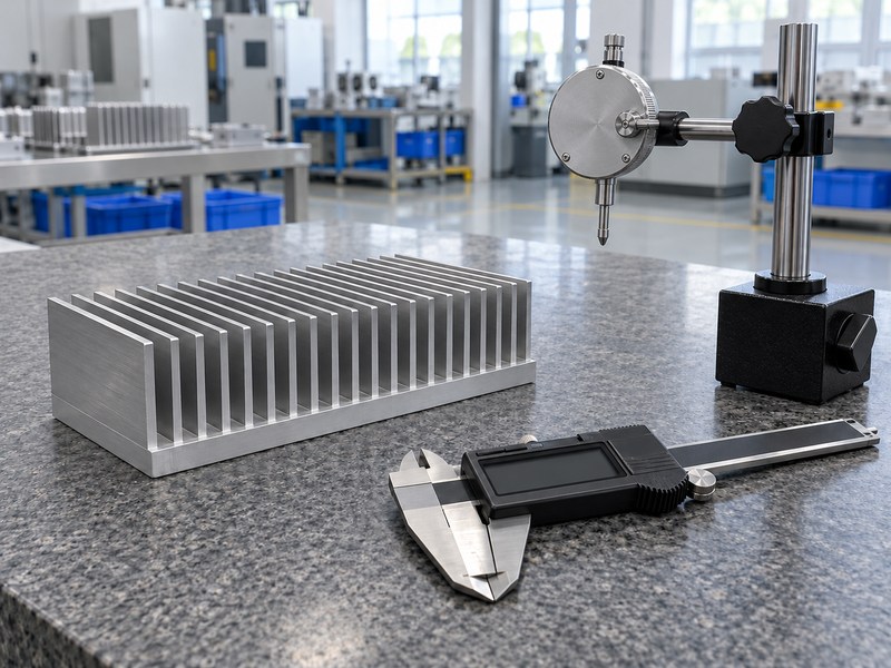
Size controls a dimension, flatness controls one surface’s form, and parallelism controls orientation relative to a datum. A shape accuracy radiator aluminum heat sink can meet its base thickness limit while the contact face remains curved. It can also have two individually flat faces that are tilted relative to each other. Specify the characteristic that represents the actual requirement rather than using a size tolerance as a substitute.
What does the inspection setup establish?
A flatness tolerance defines a surface between two parallel limiting planes without referencing a datum. Parallelism adds a reference orientation. The distinction affects fixturing and data evaluation; a height variation measured from an unrelated support surface can combine tilt and surface form.
- Distinguish local thickness checks from surface-form evaluation.
- Define the datum scheme for orientation and feature location.
- Agree how the measurement data will be aligned and evaluated.
| Control | What it addresses | Datum reference |
|---|---|---|
| Size | A specified dimension | Depends on the dimensioning scheme |
| Flatness | Form of one surface | Not required for the flatness control |
| Parallelism | Orientation of a controlled feature | Required |
Use the flatness and parallelism definitions to check that the specified control and inspection report describe the same characteristic.
4. How does extrusion die design affect the shape?
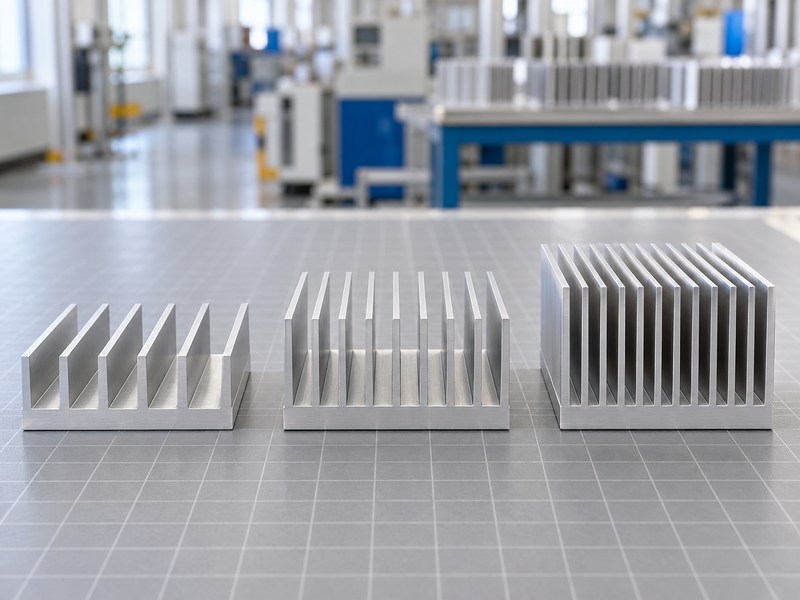
The extrusion die influences cross-sectional geometry through its opening, bearing regions, and control of metal flow. A shape accuracy radiator aluminum heat sink with thin fins beside a thick base presents a different production challenge from a simple solid section. Uneven flow and insufficient tool support can contribute to profile distortion. Nominal geometry therefore needs a manufacturability review before the die is ordered.
Which geometry should the supplier review?
Ask about the complete fin-and-base section, including narrow passages and slender die features. Compare alternatives that preserve the thermal function while making the section easier to produce. A modest change in fin spacing, height, or base geometry may be preferable to repeated correction of a difficult tool.
- Review the fin height, thickness, spacing, and root geometry together.
- Identify where the design permits a dimensional tradeoff.
- Define which surfaces will receive later machining.
| Profile feature | Production concern | Design discussion |
|---|---|---|
| Tall thin fins | Slender tooling features | Height and spacing options |
| Thick base beside thin fins | Unequal flow demands | Section balance |
| Critical mounting surface | Finished geometry | Machining allowance |
Ask for representative capability evidence from a comparable profile rather than assuming every extrusion follows the same tolerance range.
5. Why can bow and twist appear after forming?
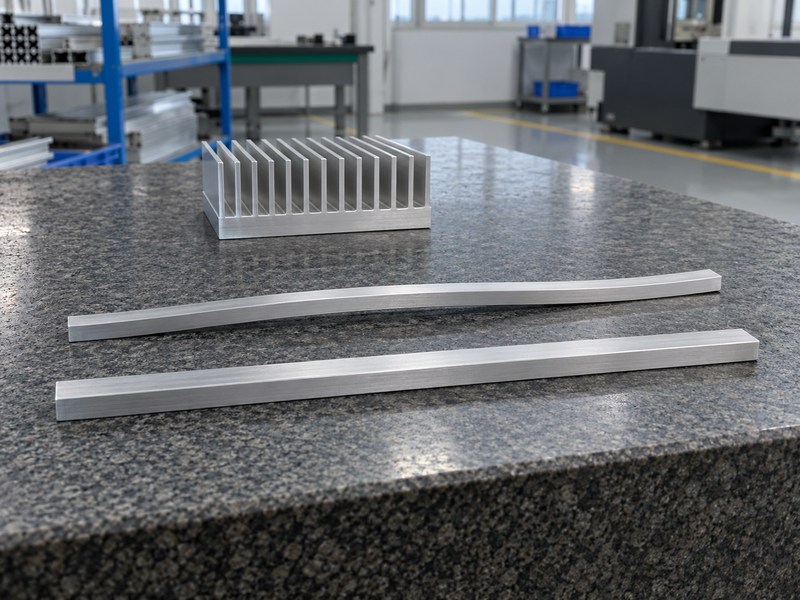
Bow and twist can develop when deformation, cooling, residual stress, and handling do not remain uniform through the part. A shape accuracy radiator aluminum heat sink can also move after material removal or a later process. Separate cross-sectional accuracy from changes along the length. A correct end profile does not prove that a long mounting face or guide edge stays within its form limit.
What should the process comparison capture?
Measure representative parts at agreed stages, such as after extrusion finishing, machining, and surface treatment. Keep the support arrangement and evaluation method consistent so differences do not come from the inspection setup. If a part changes after unclamping, investigate the restraint and material-removal sequence before tightening the drawing limit.
- Record where the part is supported during inspection.
- Distinguish unloaded geometry from the assembled condition.
- Protect thin fins during transport and machining.
| Observation | Compare | Possible investigation |
|---|---|---|
| Lengthwise bow | Multiple stations along the part | Process and handling history |
| Twist | Section orientation along the length | Restraint and straightening |
| Change after machining | Clamped and released conditions | Fixture load and residual stress |
Retain the before-and-after measurements with the drawing revision when process changes are being qualified.
6. When should you machine the base and mounting features?
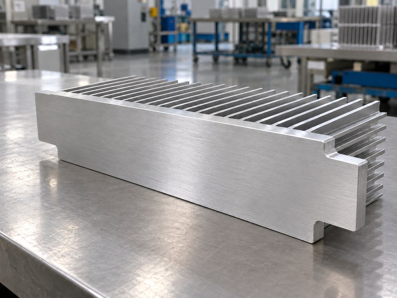
Machine those features when the as-produced geometry cannot reliably meet the finished functional limits. For a shape accuracy radiator aluminum heat sink, machining may address a contact plane, locating shoulder, or fastener pattern. It also adds fixturing, material removal, and inspection work. Specify the needed finished geometry before choosing a machining operation solely because the surface looks more precise.
What must remain after machining?
Preserve enough base material for heat spreading and mechanical support. Define a workholding approach that restrains the rigid regions without bending the fin bank. A flat face produced under heavy fixture pressure may move when released, so acceptance should use the stated inspection condition.
- Specify the finished base thickness and relevant datums.
- Keep clamps and toolpaths clear of delicate fins.
- Evaluate geometry after the workholding load is removed.
| Machined feature | Intended result | Associated check |
|---|---|---|
| Contact plane | Defined interface geometry | Flatness and texture |
| Mounting holes | Controlled assembly location | Position and edge condition |
| Locating shoulder | Repeatable seating | Orientation and fit |
Review base contact and heat spreading together; reducing base thickness can affect the thermal design even when the finished face meets its geometric limit.
7. How should you inspect the base and fin geometry?
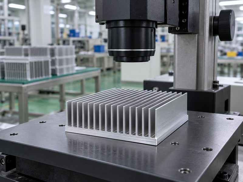
Use an inspection method that can resolve the specified characteristic without distorting the part. A shape accuracy radiator aluminum heat sink may need surface data, cross-sectional measurements, and hole-location checks from different instruments. A caliper reading at one location cannot establish the flatness of an entire contact region. Instrument capability, access, support, and evaluation rules belong in the inspection plan.
How much surface should you measure?
Select measurement coverage around the device footprint and other functional regions. Sparse points can miss a local high spot or a valley between sampling positions. More data can improve coverage, but a dense scan still needs suitable alignment, filtering, uncertainty, and acceptance rules.
- Agree on point locations or scanning coverage.
- Account for instrument access between narrow fins.
- Keep contact force low enough for the feature being measured.
| Characteristic | Possible method | Limitation to review |
|---|---|---|
| Contact-face form | CMM or suitable optical measurement | Coverage and evaluation |
| Fin spacing | Optical or accessible dimensional measurement | Fin deflection and access |
| Hole location | Datum-based coordinate measurement | Fixturing and reference alignment |
Request measured values and the inspection condition, not a report that gives only a pass label.
8. How does tolerance stack-up affect enclosure fit?
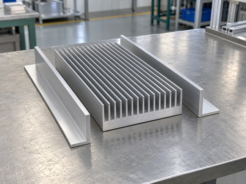
Tolerance stack-up determines whether permitted variations in mating parts leave enough clearance. A shape accuracy radiator aluminum heat sink that meets its own drawing can still bind if the enclosure’s limits were evaluated separately. Include guide alignment, part straightness, finish condition, and any temperature-dependent dimensional change where they affect installation. Check the longest engagement region rather than only the entry opening.
What does a simple clearance calculation show?
Assume a finished heat sink width of 100.00 ±0.20 mm and an enclosure opening of 100.80 ±0.15 mm. The smallest opening is 100.65 mm and the largest heat sink is 100.20 mm, leaving 0.45 mm total width clearance. This illustrative calculation assumes parallel rigid surfaces; it does not allocate clearance to each side or account for bow, misalignment, or fasteners.
- Calculate the limiting combination of mating dimensions.
- State whether the clearance is total or per side.
- Review the guide arrangement in the heat sink enclosure assembly.
| Illustrative input | Limit used | Result |
|---|---|---|
| Enclosure opening | 100.65 mm minimum | Available width |
| Heat sink width | 100.20 mm maximum | Occupied width |
| Total clearance | Opening minus heat sink | 0.45 mm |
Allocate the remaining clearance to the actual assembly conditions before approving the individual drawings.
9. What can surface finishing change at the interface?
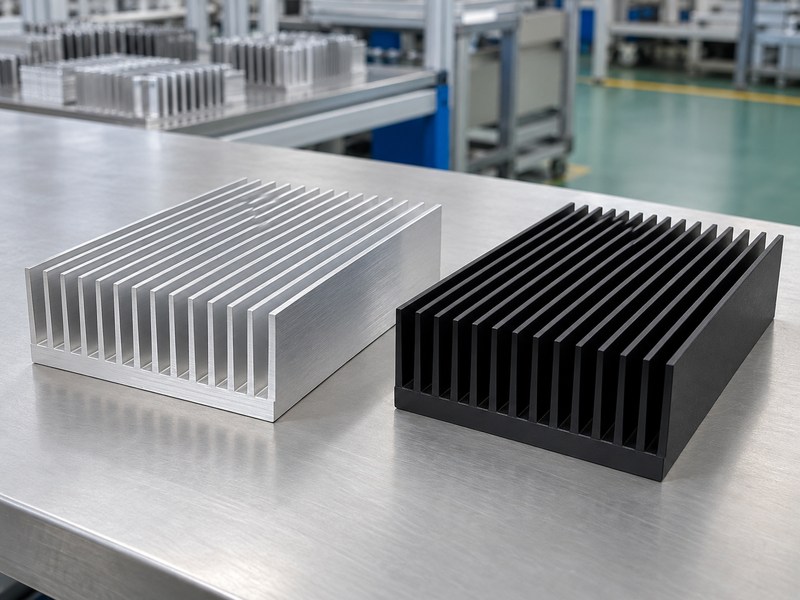
Finishing can change surface condition and finished dimensions at mating features. A shape accuracy radiator aluminum heat sink drawing should identify which limits apply after coating and which surfaces require masking. Anodizing involves both oxide formation and dimensional change, so total coating thickness should not be treated automatically as equal outward growth. Obtain process-specific information from the finishing supplier.
Which contact conditions need review?
The thermal interface depends on both mating surfaces, their form, and the selected interface material. A polished appearance does not establish flatness. A compliant pad can accommodate some geometric variation, but its compressed thickness and resistance must remain within the thermal and mechanical design limits.
- Mark thermal-contact and electrical-bonding regions separately.
- Define the finished condition for holes and guide surfaces.
- Review thermal pad compression against the permitted gap.
| Surface function | Finish requirement | Finished-part check |
|---|---|---|
| Thermal contact | Specified coating or masking | Form and interface stack |
| Sliding fit | Controlled finished dimensions | Mating clearance |
| Electrical bond | Defined contact treatment | Complete bonding path |
Inspect after the last process that can change an accepted feature, including any later assembly operation that loads the base.
10. What should you approve before volume production?
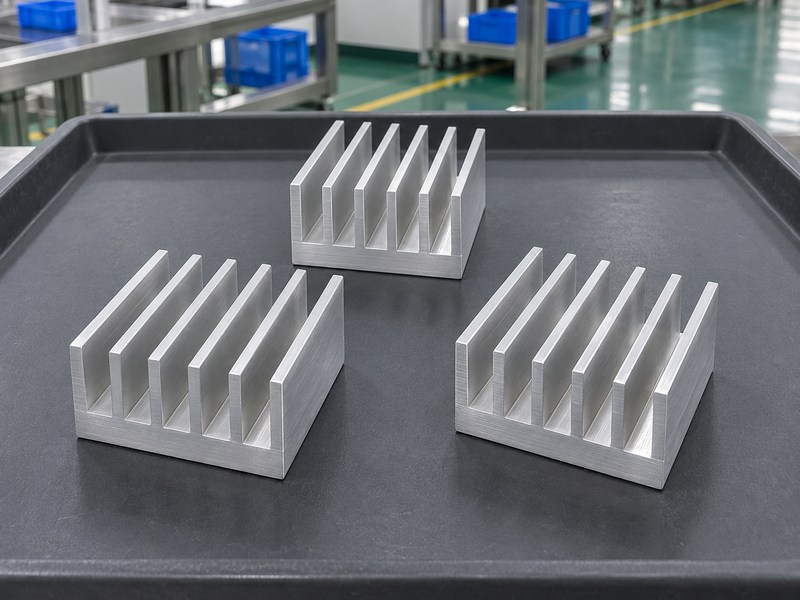
Approve representative finished parts, an inspection plan, and the manufacturing conditions tied to those parts. A shape accuracy radiator aluminum heat sink order needs more than an accepted sample with an unknown process history. Record the material condition, drawing revision, finishing requirements, and measurements of the functional features. Agree how changes in tooling, workholding, material source, or processing will trigger another review.
What evidence belongs in the release package?
Combine dimensional evidence with the relevant assembly and thermal checks. The inspection report should connect measured features to the drawing and identify the measurement condition. For repeated supply, define sampling, traceability, and the response to a result outside the agreed limit.
- Retain the approved drawing and measured sample records.
- Document the finished assembly used for thermal validation.
- Agree on lot checks and process-change notification.
| Release record | Required connection | Purpose |
|---|---|---|
| Dimensional report | Drawing features and limits | Verify geometry |
| Assembly check | Mating parts and finished condition | Verify fit |
| Thermal validation | Load, interface, and airflow | Verify operating result |
Send your drawing, contact footprint, mating-part limits, heat load, and expected volume when you contact us. Those inputs let the review connect geometric limits with the part’s manufacturing route and installed function.
FAQ
Q1: Can I put the same tight tolerance on every dimension?
You can specify it, but each limit needs a functional reason and a capable process. Separate close interface requirements from dimensions that can tolerate more variation.
Q2: Can an extruded base meet the requirement without machining?
Sometimes. Ask for capability evidence on a comparable profile and inspect the finished part against your actual contact-face requirement.
Q3: How do I know whether the issue is bow or flatness?
Define the feature and evaluation length. Bow describes curvature along a length, while a flatness control evaluates the specified surface within a two-plane zone.
Q4: Can a caliper prove that the mounting base is flat?
No. Local dimensional readings do not establish whole-surface form; use a suitable form-measurement method and defined coverage.
Q5: What’s the best stage for the acceptance inspection?
Inspect the finished condition stated on the drawing. Use checks before and after sensitive operations when you need to understand which process introduces variation.