
Choose bendable aluminum sheet by alloy, temper, bend geometry, and the thermal resistance your assembly can tolerate. A sheet metal bending aluminum heat sink can fit a narrow enclosure, yet a cracked flange or bowed mounting face can turn a low-cost part into a cooling problem. Start with the heat load and contact footprint, then qualify the material and forming process together.
1. What is a sheet metal bending aluminum heat sink?
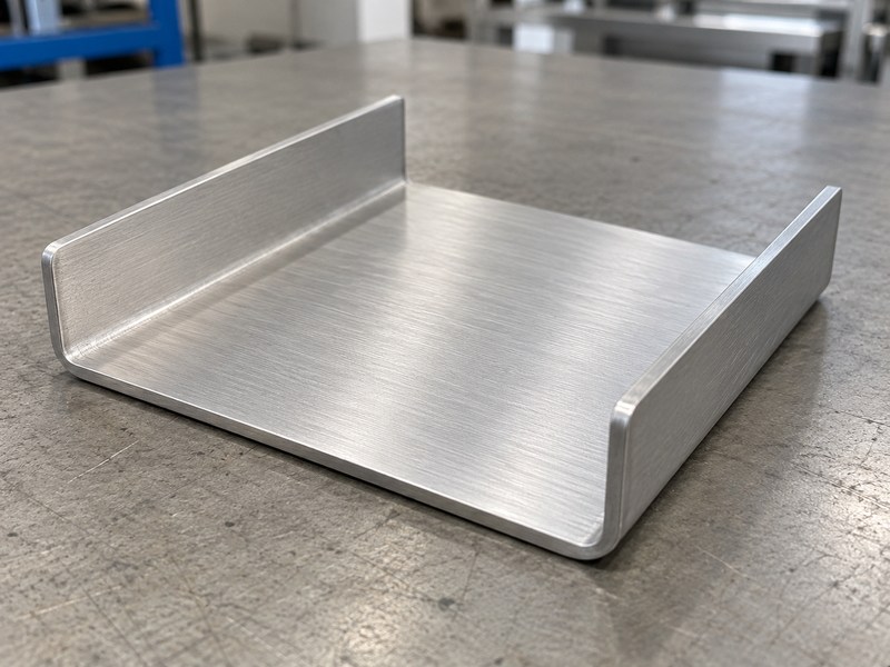
A sheet metal bending aluminum heat sink is a formed metal part that conducts heat from a mounting area into exposed sheet surfaces. Its geometry may be an L section, a U channel, or a stamped shape with several tabs. The base and flanges usually share one sheet thickness, which constrains how much metal you can place beneath a concentrated heat source. You gain freedom around enclosure features, but must check heat spreading across that thin base.
Which construction are you specifying?
Bending a sheet and curving an existing extruded profile require different tooling and qualification. An extrusion already has its base and fins; bending it can alter fin spacing and the mounting surface. A folded-fin assembly adds another distinction because a separate fin strip joins a base through an attachment process.
- Specify whether the part begins as sheet, extrusion, or separate fins.
- Mark the heat-source footprint and intended mounting face.
- Show enclosure obstructions before selecting flange height.
| Construction | Forming concern | Thermal concern |
|---|---|---|
| Bent sheet | Bend integrity | Thin-base spreading |
| Curved extrusion | Profile distortion | Fin clearance |
| Separate folded fins | Fin attachment | Joint resistance |
Choose the construction before comparing quotations; the same outside envelope can hide different heat paths.
2. Which aluminum alloy and temper should you choose?
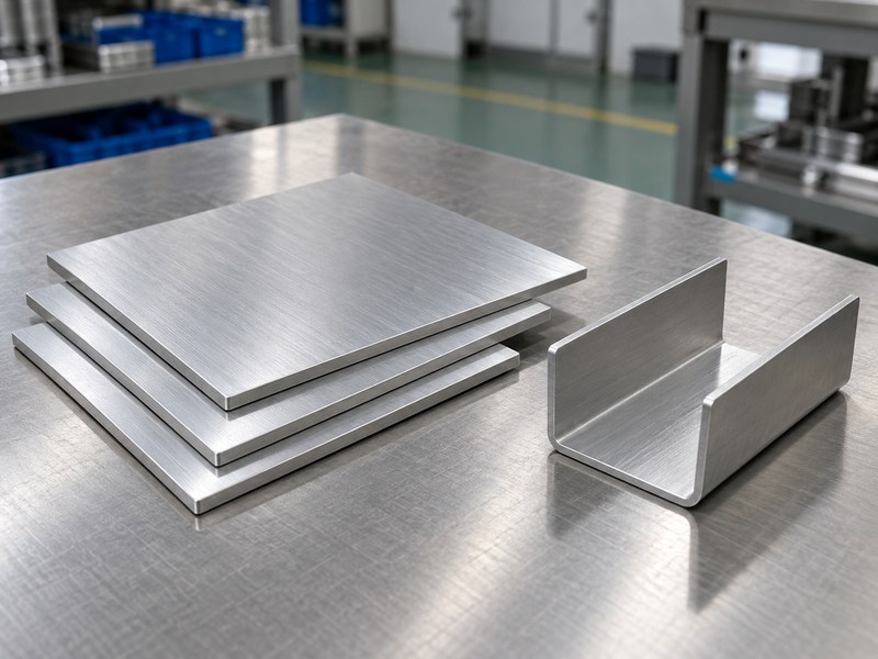
Choose an alloy and temper with enough formability for your bends, then verify its conductivity and strength against the application. For a sheet metal bending aluminum heat sink, material identification must include temper and thickness rather than an alloy number alone. Sheet certificates and material-specific bend recommendations provide a starting point. A production-like coupon test checks whether that starting point suits your tools and grain orientation.
What belongs on the material specification?
Commercially pure aluminum and 3003 sheet can suit designs that prioritize formability and heat conduction over strength. A 5052 sheet may fit an assembly that needs more mechanical strength or corrosion resistance. A hardened 6061 condition calls for particular care because a tight bend may crack even when the flat stock meets its strength requirement.
- Request the alloy, temper, thickness tolerance, and material certificate.
- Record rolling direction relative to each bend line.
- Qualify the actual condition used for production.
| Selection factor | Ask the supplier for | Verify on the part |
|---|---|---|
| Formability | Bend guidance by temper | Outer-bend condition |
| Conductivity | Material-specific data | Temperature distribution |
| Strength | Relevant property limits | Mounting stability |
A softer condition may simplify forming, but any later heat treatment requires its own process and dimensional checks.
3. How do you set bend radius and flat-pattern allowance?
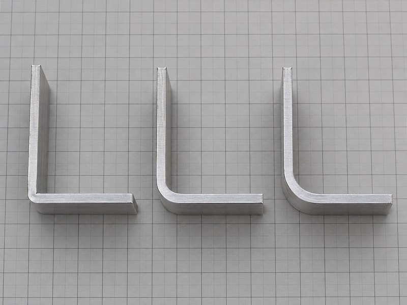
Set the inside bend radius from material condition, thickness, grain direction, and trial results, then calculate the flat pattern using qualified tooling data. A sheet metal bending aluminum heat sink needs enough radius for forming without consuming the flat area reserved for thermal contact. A universal radius-to-thickness rule can miss the actual alloy condition. Keep the device footprint clear of the curved transition and its manufacturing tolerance.
How can you check the bend allowance?
For a preliminary calculation, bend allowance equals the bend angle in radians multiplied by the inside radius plus K times thickness. Assume a 90-degree bend, a 3 mm inside radius, 2 mm sheet, and an illustrative K factor of 0.4. The allowance is approximately 5.97 mm; the K factor is an assumption that requires calibration on the chosen process.
- State whether dimensions reference inside, outside, or tangent features.
- Add bend relief where intersecting features would tear.
- Use the shop’s measured bend deductions for production drawings.
| Example input | Assumed value | Purpose |
|---|---|---|
| Bend angle | 90 degrees | Arc calculation |
| Inside radius | 3 mm | Geometry input |
| Thickness and K | 2 mm; 0.4 | Neutral-axis estimate |
The calculated allowance predicts developed length; it does not prove the material can survive that radius.
4. Which tooling prevents cracks and surface damage?
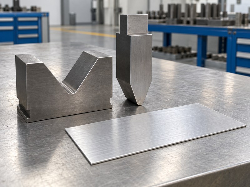
Use tooling that supports the required radius and flange length without marking or overloading the aluminum. A sheet metal bending aluminum heat sink can pass an angle check while carrying scratches or small edge cracks that compromise handling and durability. Tool selection must account for sheet thickness, die opening, punch shape, machine capacity, and the available bend sequence. A polished contact surface helps protect a cosmetic face, but does not correct an unsuitable radius.
What should a forming trial reproduce?
Run a coupon or representative blank through the intended tool setup. Include nearby holes, cutouts, and short flanges when those features affect support. Check cut edges before bending because a burr or deep scratch can create a local strain concentration along the outside surface.
- Deburr the blank and remove embedded particles.
- Verify punch clearance through the complete bend sequence.
- Inspect the outside bend under suitable magnification.
| Observed defect | Check before adjusting | Possible change |
|---|---|---|
| Outside cracking | Temper and radius | Larger radius or different stock |
| Die marks | Surface cleanliness | Tool protection |
| Distorted hole | Hole-to-bend location | Relocated feature |
Use controlled process changes. Local torch heating can change material properties and needs qualification before it becomes a production method.
5. How do you control springback and base flatness?
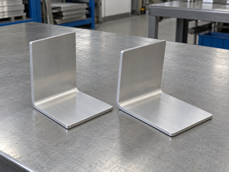
Control springback through measured tool compensation and protect base flatness through the bend sequence and part support. A sheet metal bending aluminum heat sink must fit its assembly after unloading, rather than only while held in tooling. Springback varies with material condition and geometry, so a fixed compensation angle rarely transfers reliably across every job. Measure the free part from defined datums before changing the machine program.
Which dimension affects thermal contact?
The mounting face deserves a separate flatness requirement. Tightening a bowed sheet against a rigid device may distort the package or leave gaps at the interface. A thicker thermal pad can accommodate some variation, but it also changes the thermal path and clamp behavior; review the thermal pad selection alongside the mechanical drawing.
- Inspect flange angle after release from the tool.
- Measure mounting-face flatness without forcing the part flat.
- Check whether assembly torque changes the contact pattern.
| Characteristic | Measurement condition | Acceptance basis |
|---|---|---|
| Flange angle | Unloaded part | Drawing tolerance |
| Base flatness | Defined support | Interface needs |
| Assembled shape | Specified clamp load | Device limits |
Repeat those checks across representative material lots before treating a compensation setting as stable production data.
6. Can bent sheet meet your thermal resistance target?
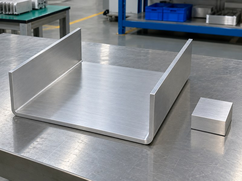
Bent sheet can meet the target when its complete heat path stays within the permitted temperature rise. For a sheet metal bending aluminum heat sink, that path includes the device interface, heat spreading through the base, and heat rejection from exposed surfaces. Calculate the allowable resistance before selecting the part by surface area. A small contact footprint can create a hot spot even when the surrounding sheet remains relatively cool.
What does a preliminary thermal budget look like?
Assume a device dissipates 20 W, the permitted mounting-case temperature is 85°C, and local inlet air reaches 45°C. The case-to-air budget is 2.0°C/W, calculated as the 40°C temperature rise divided by 20 W. If the interface consumes an assumed 0.3°C/W, the remaining sink-to-air budget is 1.7°C/W; this example predicts a requirement, not a tested part rating.
- Use worst-case dissipation and air temperature at the assembly.
- Include interface resistance and spreading effects.
- For a junction limit, include junction-to-case resistance too.
| Illustrative quantity | Value | Interpretation |
|---|---|---|
| Dissipation | 20 W | Assumed operating load |
| Case-to-air budget | 2.0°C/W | Available resistance |
| Sink-to-air budget | 1.7°C/W | After assumed interface loss |
If sheet construction misses the target, compare thicker-base alternatives before adding flanges that available airflow cannot use.
7. How should airflow and flange geometry work together?
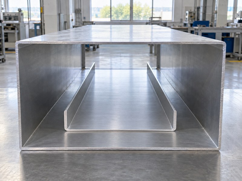
Arrange flanges so air can enter, pass the heated surfaces, and leave without excessive bypass or blockage. A sheet metal bending aluminum heat sink installed beside cables or enclosure walls may behave differently from the same part on an open bench. Taller surfaces add area, but the temperature along a thin flange falls as heat travels away from the base. Fin efficiency and local flow determine how much of that area contributes.
What changes inside an enclosure?
A fan’s free-air rating does not describe the flow through your assembled channel. Vents, filters, bends, and neighboring components create resistance and can divert air around the part. With natural convection, orientation and an open buoyancy path influence performance, so test the intended installed position.
- Keep entrances and exits clear of brackets and wiring.
- Evaluate the fan and system resistance together.
- Check dust accumulation and the service access needed for cleaning.
| Installation factor | Possible effect | Useful verification |
|---|---|---|
| Narrow passage | Higher resistance | Flow or pressure check |
| Bypass gap | Less surface flow | Enclosure-level test |
| Changed orientation | Different convection | Repeat thermal test |
Use the actual enclosure in qualification. An isolated heat-sink result leaves these interactions unresolved.
8. How do you mount the heat source without distortion?
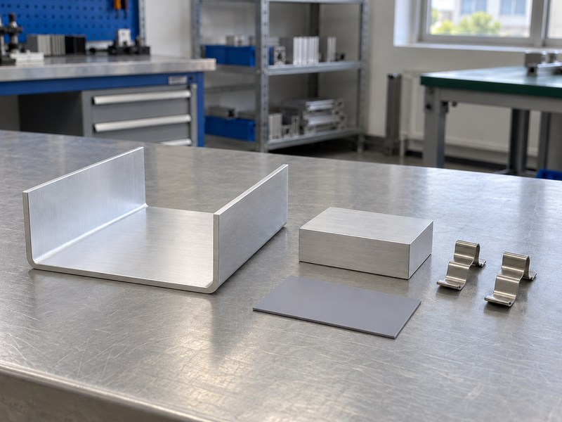
Mount the heat source against a flat contact area with a defined interface material and controlled clamp load. A sheet metal bending aluminum heat sink can flex under a screw or clip, so the fastening pattern must support the device footprint. Position holes away from bend deformation zones and provide tool access after assembly. If an electrically live device tab touches the heat sink, review isolation across the complete mounting stack.
What should the assembly drawing control?
Specify the interface material, thickness or applied amount, fastener type, and tightening procedure. A nominal torque value alone does not define contact pressure because thread condition and hardware affect clamp load. Review the mounting arrangement against the component manufacturer’s mechanical limits and the interface supplier’s compression guidance.
- Define the flat contact region and allowable surface defects.
- Include washers, spacers, or insulation where the design requires them.
- Check that hardware cannot bridge an intended electrical barrier.
| Assembly item | Drawing information | Failure to check |
|---|---|---|
| Interface | Material and application | Excess gap or poor contact |
| Fastener | Type and tightening method | Local sheet distortion |
| Isolation | Complete hardware stack | Electrical contact path |
Test the assembled stack after service-like loading or temperature cycling when those conditions belong to the application.
9. When should you finish, stamp, or change the process?
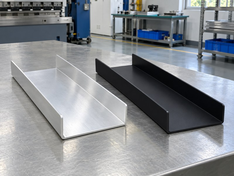
Select finishing and manufacturing sequence after the bend geometry and thermal interface have been qualified. A sheet metal bending aluminum heat sink may use laser-cut blanks for prototypes and dedicated stamping tools for a stable higher-volume design. Tooling cost, feature complexity, scrap, and inspection effort determine whether that change pays back. Compare total delivered cost rather than the forming price alone.
Which surfaces need a finish specification?
Anodizing can provide corrosion protection and change radiative heat transfer, but its thermal benefit depends on operating conditions. The coating also changes contact and electrical behavior, so specify any masking on mounting or bonding surfaces. Bending after a finish can damage it; bending before finishing requires allowance for the later process and its effect on dimensions.
- Identify cosmetic, contact, and electrical-bonding surfaces separately.
- Require finish samples when appearance affects acceptance.
- Compare folded-fin construction when separate fins suit the thermal design.
| Decision | Favor the change when | Recheck |
|---|---|---|
| Dedicated stamping | Stable volume supports tooling | Part consistency |
| Post-form finish | Coating must cover bends | Contact surfaces |
| Different construction | Thermal target is missed | Complete assembly |
Quote competing processes against the same drawing revision and thermal acceptance condition so the cost comparison remains useful.
10. What should you test before approving production?
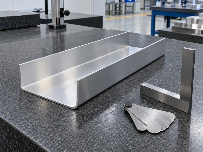
Approve production after representative parts meet dimensional, material, assembly, and thermal acceptance criteria. A sheet metal bending aluminum heat sink needs evidence from the finished assembly because forming, finishing, and clamping can each affect contact or airflow. Define the input power, inlet-air temperature, orientation, and measurement locations before comparing samples. Record the time or stability criterion used to judge the temperature result.
What belongs in the release package?
Request a drawing-linked inspection report and retain the qualified material and process conditions. Include bend condition, base flatness, finish requirements, and the agreed thermal test. Decide how changes in material source, tooling, or finishing trigger review rather than assuming a visually similar part will behave identically.
- Check the finished part and the assembled contact stack.
- Record thermal conditions alongside the temperature measurements.
- Define lot sampling, traceability, and change notification.
| Release evidence | Minimum content | Acceptance reference |
|---|---|---|
| Dimensional report | Datums and measured features | Approved drawing |
| Material record | Alloy, temper, lot | Purchase specification |
| Thermal report | Load, air, assembly, temperatures | Agreed operating limit |
Send the drawing, heat load, contact footprint, available airflow, and annual volume when you contact us. Those inputs let the design review address bend feasibility, mounting, and cooling against one set of requirements.
FAQ
Q1: Can I bend an existing extruded aluminum heat sink?
Sometimes. The profile, temper, curve, and fin geometry need a specialist review because bending can distort the base and close the air passages.
Q2: What’s the best aluminum alloy for a bent heat sink?
There is no single best alloy. Compare formability, conductivity, strength, corrosion exposure, and finish requirements using the specified temper and thickness.
Q3: How do I know if the bend radius is safe?
Check material-specific guidance and qualify a representative bend. Inspect the outside surface and verify dimensions using the production tooling and grain orientation.
Q4: Can black anodizing replace a larger heat sink?
Usually it cannot justify that change by itself. Its effect depends on radiation, temperature, airflow, and coating details; test the complete assembly before reducing size.
Q5: Can I use a thicker pad to cover a bowed base?
Only if the resulting thermal and mechanical stack meets your limits. A thicker pad can accommodate variation, but its resistance and compression must enter the design review.