
Make a stainless steel CNC milling heat sink base from a drawing that defines the heat path, contact surfaces and inspection datums. A flat-looking plate can still leave a poor thermal interface. Establish those requirements before choosing stock thickness, pockets or a machining sequence.
1. What must a stainless steel CNC milling heat sink base do?
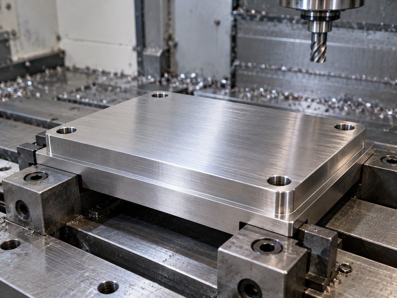
A stainless steel CNC milling heat sink base must carry heat through a defined path while supporting the mounting and assembly loads. It may spread heat, connect a component to fins or support another cooling part. Define which surfaces perform those jobs rather than treating every face as equally critical.
Put the source layout on the drawing
Show the location and size of each heat source, including sources that operate together. A small source near an edge produces a different spreading problem from the same load centered on the base. Keep the actual contact footprint visible when deciding where material can be removed.
Separate thermal requirements from cosmetic requirements in the inspection plan. A smooth outer face does not establish the flatness or contact area needed beneath the component, and an unused decorative recess should not consume material beneath a hot spot.
- Identify source footprints and operating heat loads.
- Mark the contact and mounting surfaces by function.
- State which loads pass through the base and its fasteners.
| Base function | Drawing information | Acceptance focus |
|---|---|---|
| Heat transfer | Source and exit locations | Temperature rise |
| Mounting | Package and fastener stack | Contact without damage |
| Support | Load path and orientation | Stiffness and retention |
Agree on these functions before using an existing plate as the production reference.
2. Which stainless stock and condition should you choose?
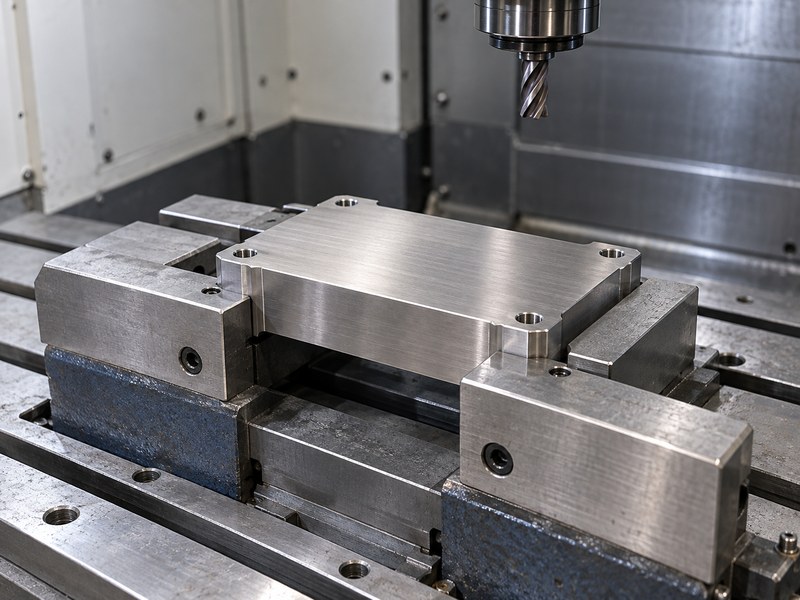
Choose stock using the material, exposure and manufacturing requirements of the stainless steel CNC milling heat sink base. Grade, product form and supplied condition affect the machining plan. A material substitution can also change thermal and corrosion behavior even when the drawing’s outer dimensions stay the same.
Ask how the stock will reach its final condition
Use grade-specific stainless material properties where relevant, and connect the supplied stock to its agreed traceability record. Ask the manufacturer to explain its allowance for roughing, stress movement and finishing. Those decisions depend on geometry and the chosen material rather than a universal stock allowance.
Stainless machining can create heat, work hardening and tool-wear challenges. Have the manufacturer select a suitable cutting strategy and verify that it produces the specified geometry and surface condition; do not copy a feed or speed from a different alloy without review.
- State the accepted grade, condition and product form.
- Define the policy for equivalent material or stock substitutions.
- Include all later cleaning, joining and finishing operations in the plan.
| Stock detail | Affects | Confirm with the supplier |
|---|---|---|
| Grade and condition | Properties and cutting behavior | Available production material |
| Initial thickness | Machining allowance and movement | Proposed roughing route |
| Later processing | Final geometry and surface | Inspection after all operations |
Release the material route with the drawing so production does not rely on an unstated assumption.
3. Which contact-face tolerances affect heat transfer?
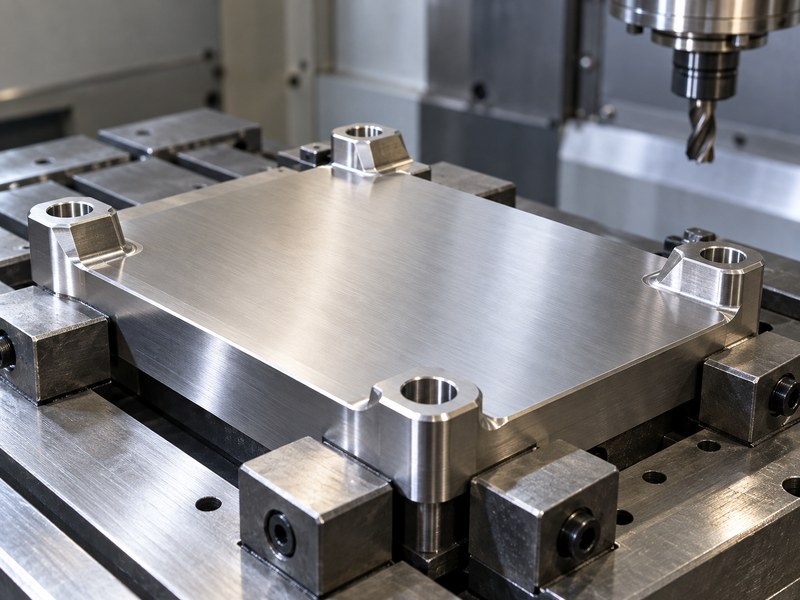
Contact-face geometry on a stainless steel CNC milling heat sink base affects the interface gap and pressure distribution. Flatness describes overall form, while roughness describes surface texture at a different scale. A low roughness value does not prove the whole contact face is flat.
Derive the requirement from the assembly
Select tolerances with the component footprint, interface material and available clamping load in mind. A small hard contact and a larger compliant pad can require different surface control. Making every face mirror-bright can add cost without addressing the actual contact problem.
Write flatness as an appropriate geometric requirement rather than an unexplained plus/minus surface value. Define the evaluated area and the final inspection condition, including whether a thin part is free or constrained during measurement.
- Separate flatness, roughness and dimensional requirements.
- Identify surfaces that must remain uncoated or free of residue.
- Check the mating component and compressed interface thickness.
| Requirement | Describes | Does not establish alone |
|---|---|---|
| Flatness | Overall surface form | Texture or cleanliness |
| Roughness | Local surface texture | Global flatness |
| Thickness | Distance between defined faces | Uniform assembly contact |
Specify only the controls that support fit, contact or the required inspection method.
4. How should datums and workholding be arranged?
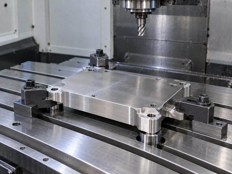
Arrange datums and workholding so the stainless steel CNC milling heat sink base can be machined and inspected in a repeatable state. A fixture can hold a thin plate flat during cutting while the released part springs into a different shape. The drawing and inspection plan need to address the condition that matters in service.
Locate the part without unnecessary restraint
A suitable 3-2-1 locating scheme can establish a primary plane, secondary direction and final position when the geometry permits it. The contact locations and clamp forces still need to suit the actual part. Avoid pressing through a flexible region simply because it is easy for the fixture to reach.
Ask how the manufacturer changes setups and transfers datums between operations. The final contact face, hole pattern and mounting features must relate to the same functional reference rather than to whichever raw edge is convenient in each setup.
- Support the part near the loads that could bend it.
- Keep clamp contact away from fragile features and finished interfaces.
- State the measurement condition for free-state or mounted geometry.
| Fixture element | Purpose | Check |
|---|---|---|
| Primary support | Establishes the base plane | Stable contact without rocking |
| Side and end location | Controls lateral position | No conflicting restraint |
| Clamping | Holds the part against locators | No harmful distortion |
Use the same functional datum logic when reviewing the final inspection result.
5. Which pockets and corners are practical to mill?
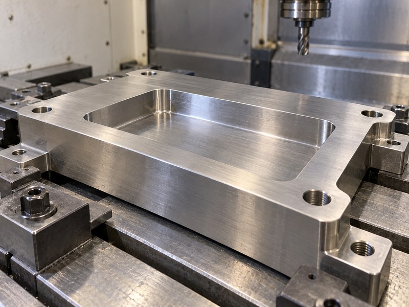
Pockets and corners in a stainless steel CNC milling heat sink base are practical when the tool can reach them and remove chips without creating unstable thin walls. Internal radii follow cutter geometry. A sharp internal square corner may require a different process or a design change.
Preserve the material that carries heat and clamp load
Pocketing can reduce mass, but removing material beneath a source changes both conduction and stiffness. Check the remaining thickness and the load path around mounting holes. A pocket that clears a neighboring part may be useful, while a decorative pocket beneath a hot spot may create a thermal penalty.
Review deep features with the manufacturer before freezing the model. Tool reach, deflection, chip evacuation and deburring access can make a small geometric detail expensive or inconsistent across a batch.
- Allow practical internal radii where the mating part permits them.
- Keep access for chip removal and final cleaning.
- Review thin floors and walls in their released condition.
| Feature | Concern | Useful design review |
|---|---|---|
| Deep pocket | Long tool reach | Depth, width and cutter access |
| Thin floor | Movement under load | Thermal and stiffness requirement |
| Small internal corner | Process limitation | Radius or alternative operation |
Compare a geometry change with the full thermal and assembly requirement before accepting it for lower machining cost.
6. How should mounting holes and threads be specified?
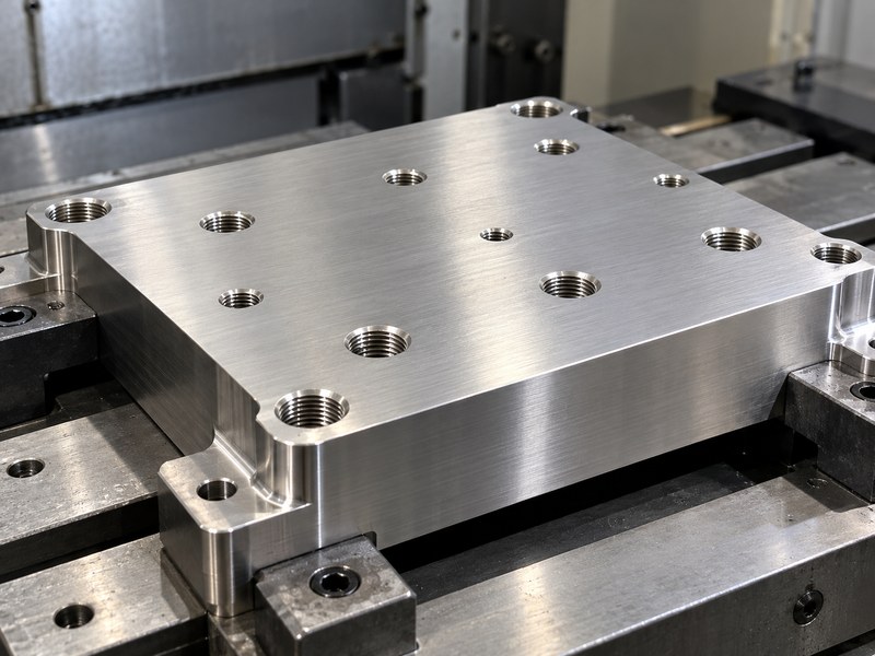
Specify holes and threads on a stainless steel CNC milling heat sink base so fasteners locate, retain and clamp the intended stack. A blind screw can bottom out before it applies the required load. A through-hole can create an unwanted opening or interfere with another component if its full path is not reviewed.
Check the fastener stack at both limits
Use the actual screw length, engagement, washers and interface thickness in the stack review. Include manufacturing tolerances rather than checking the nominal model alone. Identify holes that require a defined orientation, counterbore or clearance from nearby features.
The inspection plan should distinguish hole position, size and usable thread depth. A clean-looking entry does not prove the full thread is usable, and debris left in a blind feature can change the assembly behavior.
- Check screw engagement and bottoming across tolerance limits.
- Provide suitable entry details and burr control.
- State whether a hole must remain blind for the assembly design.
| Hole requirement | Controls | Verification |
|---|---|---|
| Position | Alignment to the assembly | Defined datum scheme |
| Usable thread depth | Fastener engagement | Suitable thread inspection |
| Clearance or counterbore | Hardware fit | Complete stack review |
Confirm the hardware and hole specification together rather than approving them in separate reviews.
7. How does the thermal interface change base design?
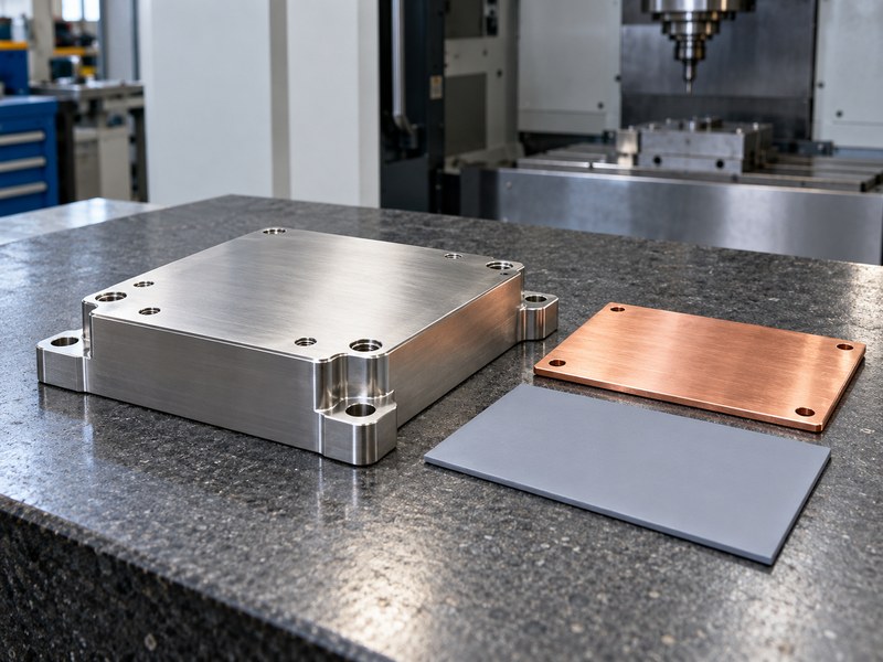
A stainless steel CNC milling heat sink base needs a controlled interface because the metal path and interface layers contribute to source temperature together. A pad can fill a designed gap, but it cannot make an arbitrary bowed surface equivalent to the specified contact geometry. Added spreaders also introduce added joints.
Use a simple calculation to locate the penalty
For an illustrative uniform path, assume 3 mm thickness, 625 mm² area and conductivity of 16 W/(m·K). The through-thickness resistance is 0.30 K/W, which produces a 6 K rise at 20 W before other losses. This model excludes lateral spreading and all interface layers.
If a copper spreader is proposed, model its contact to the base and source. Compare the assembled result instead of subtracting the steel resistance while ignoring the new joint that replaces part of it.
- Use source size and contact pressure in the interface review.
- Define the compressed pad thickness or adhesive bond line.
- Recheck the stack after thermal cycling where movement can occur.
| Heat-path item | Needs | Compare using |
|---|---|---|
| Stainless base | Grade and geometry | Actual conductive path |
| Interface layer | Thickness and contact condition | Joint resistance |
| Added spreader | Material plus its joints | Complete source temperature |
Keep every layer in the model until the assembled test supports simplifying it.
8. How should the finished base be inspected?
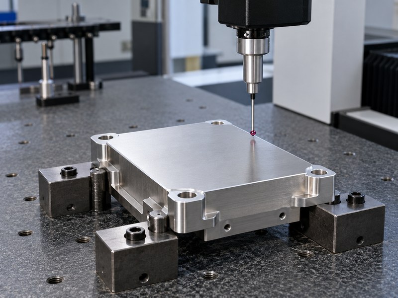
Inspect the stainless steel CNC milling heat sink base against its functional datums after the operations that can affect final geometry. Calipers, coordinate measurement, surface inspection and thread gauges serve different purposes. No single attractive inspection photograph proves all drawing requirements were met.
Match the measurement to the characteristic
State the evaluated contact area and how the part is supported during measurement. A constrained thin base can give a different form result from its free state. Where cleaning or treatment follows machining, confirm which characteristics need a final check afterward.
Inspect more than the obvious outer dimensions. Burrs, trapped debris, thread condition and damaged mating faces can affect assembly even when the part’s length and width are correct.
- Connect each critical characteristic to a suitable method.
- Record the final material and surface condition.
- Define sample and production inspection scope before ordering.
| Characteristic | Suitable inspection question | Avoided assumption |
|---|---|---|
| Contact form | Is the specified area within its limit? | Smooth means flat |
| Hole pattern | Does it relate to the functional datums? | Edge dimensions prove assembly fit |
| Thread and cleanliness | Is the feature usable as supplied? | A clear entry proves a clean hole |
Agree on the inspection report format while the drawing is still being reviewed.
9. How do you validate the base thermally?
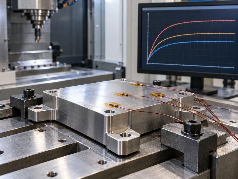
Validate a stainless steel CNC milling heat sink base with the intended source footprint, interface and heat-removal boundary. The same base can give different temperatures when attached to fins, a chassis wall or a cold plate. Record those attachments as part of the test configuration.
Check local temperature differences
Place sensors where they can answer the design question, such as near the source and near the base’s heat-exit region. Record their attachment and location so the temperature difference remains meaningful. A fin-tip reading cannot substitute for the source-side base temperature.
Use representative mounting hardware and assembly settings. If the test uses a different contact area or unusually strong fixture cooling, its result may not describe the product installation.
- Measure applied heat and identify other paths into the fixture.
- Define local air or coolant conditions and stabilization.
- Repeat mounting if contact variation could affect selection.
| Test boundary | Record | Why it matters |
|---|---|---|
| Heat source | Power and footprint | Controls local heat flux |
| Interface | Material and assembly setting | Controls contact resistance |
| Heat exit | Attached cooling part and conditions | Defines the base’s duty |
Retain the complete setup with the result before approving the production configuration.
10. What should the machining RFQ contain?
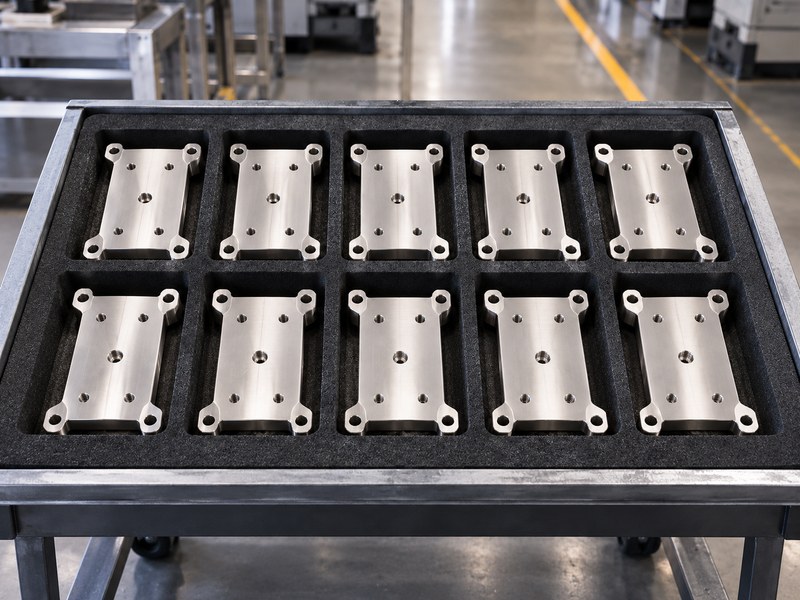
A stainless steel CNC milling heat sink base RFQ should define the material, functional geometry, thermal duty and final inspection condition. Include a model and a controlled drawing rather than letting the model stand in for every requirement. Identify the features that the supplier may change during manufacturing review.
Separate mandatory controls from preferences
Provide the source layout and mounting stack so the manufacturer can see why a face or wall thickness matters. Ask for proposed datums, workholding and final-contact-face operations when those affect risk or cost. Define sample quantities, traceability and the approval route for deviations.
Share your drawing and temperature target when you contact us. We can discuss relevant machined heat sink, interface and cold plate options before the base geometry is released for production.
- State final-condition flatness, roughness and hole requirements.
- Include the quantity and any required material records.
- Agree on a representative sample and validation plan.
| RFQ section | Provide | Response to request |
|---|---|---|
| Material | Grade, condition and substitution policy | Available production route |
| Drawing | Datums and functional tolerances | Manufacturability review |
| Validation | Thermal and inspection requirements | Comparable sample plan |
Approve the final drawing and evidence requirements together with the production sample.
FAQ
Q1: Can I use a polished surface instead of a flatness tolerance?
No. Polishing changes texture and appearance, while flatness controls overall form. Define both only where the interface needs them and specify the inspection condition.
Q2: How thin can I machine the stainless base?
The practical thickness depends on heat flow, stiffness, workholding and the geometry. Review the released part and the assembled load rather than using a universal minimum.
Q3: Can I add a copper insert to improve spreading?
Yes, if its location, joining or mounting method and interface resistance are reviewed. Compare the complete stack because an added joint can consume part of the expected benefit.
Q4: Does a base automatically qualify as a cold plate cover?
No. A pressure-boundary component needs its own design, sealing, material and qualification requirements. A passive mounting-base inspection does not establish that duty.
Q5: What should I check before accepting a sample?
Check the material record, functional geometry, usable holes, cleanliness and the agreed thermal result. Use the approved inspection and assembly condition rather than appearance alone.