
Choose a stainless steel finned heat sink by matching its construction, heat duty and airflow to the service. For a finned-tube design, also define the fluid circuit and pressure boundary. A coil can fit the enclosure while missing its cooling target, so establish those conditions before requesting a quote.
1. What construction does a stainless steel finned heat sink use?
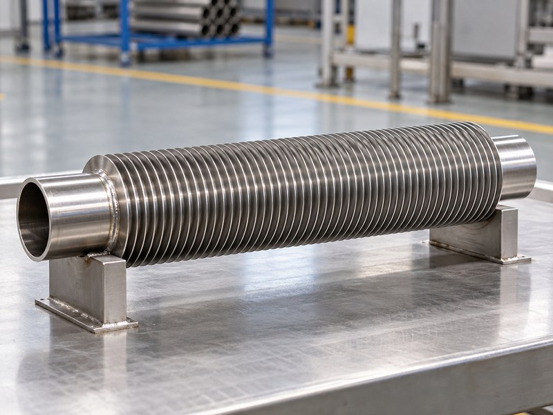
In finned-tube applications, a stainless steel finned heat sink transfers heat between fluid inside a tube and air around its fins. The tube, fin attachment and air path all contribute to performance. Confirm the drawing because the same broad product term can also describe a finned solid base.
Identify both heat-transfer boundaries
A tube coil needs defined fluid connections and air-side conditions. A finned solid base instead receives heat through a contact face from another component. The required specifications differ, even when both products have stainless fins and a similar outer size.
For a fluid-to-air coil, mark inlet and outlet conditions on the circuit drawing. Show the surrounding enclosure or duct so the supplier can evaluate how air reaches the finned surface and where it leaves afterward.
- Identify tube-coil or solid-base construction before comparing quotations.
- Define where heat enters and leaves the assembly.
- Provide the operating orientation and available air path.
| Construction detail | Defines | Needed information |
|---|---|---|
| Tube circuit | Fluid-side heat path | Fluid and connection layout |
| Fins | Air-side area and flow passages | Geometry and attachment |
| Enclosure or duct | Installed airflow boundary | Space and obstructions |
Use the construction drawing as the starting point for the thermal specification.
2. Which stainless grades belong in the tube and fins?
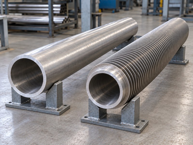
Specify the tube and fin grades separately for a stainless steel finned heat sink. The tube may contact a process fluid while the fins contact air, deposits or cleaning agents. Those exposures can justify different requirements, and the joining route may place further limits on the material pair.
Review the wetted boundary and exposed surface
Use the actual fluid chemistry, temperature and cleaning conditions when selecting the tube material. Review the air-side exposure independently, including salts, condensation and process residue. A grade suitable for one side is not automatically suitable for every condition on the other side.
Compare grade-specific stainless material properties and require the agreed traceability for supplied material. Include connection and joining materials when reviewing the pressure boundary and environmental compatibility.
- State the accepted tube, fin and connection materials.
- Identify the fluid and any cleaning or treatment chemicals.
- Define whether substitutions require renewed thermal or corrosion review.
| Component | Exposure | Purchasing control |
|---|---|---|
| Tube wall | Internal fluid and external environment | Grade and product form |
| Fin surface | Air, deposits and cleaning | Grade and surface condition |
| Joint or connection | Local chemistry and stress | Complete material specification |
Release the material combination with its intended service conditions.
3. How should the fin contact the tube?
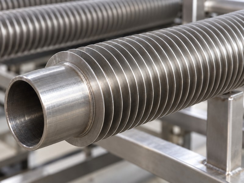
The fin-to-tube contact in a stainless steel finned heat sink must carry heat and remain stable under the intended service conditions. Winding creates mechanical contact around a tube. A metallurgical bond requires a separately specified joining route rather than the winding action alone.
Ask what holds the heat path together
Mechanical attachment, welding and other joining methods create different interfaces and inspection needs. Ask the manufacturer to identify the proposed route and the acceptance evidence. A tidy spiral appearance does not reveal the entire thermal contact beneath the fin root.
Temperature cycling, corrosion and handling can change contact or damage a joint. Qualify the production construction rather than using a different attachment method for the sample that supplies the quoted thermal result.
- Identify the attachment or joining method explicitly.
- Define accepted contact, joint and visible-condition checks.
- Include service cycling where it can affect the fin root.
| Attachment issue | Consequence | Evidence to request |
|---|---|---|
| Inconsistent root contact | Variable heat transfer | Agreed manufacturing and inspection controls |
| Damaged joint | Reduced retention or heat path | Representative qualification |
| Changed production route | Different interface behavior | Approval before substitution |
Tie the thermal result to the actual fin attachment supplied in production.
4. How should fin pitch and height be chosen?
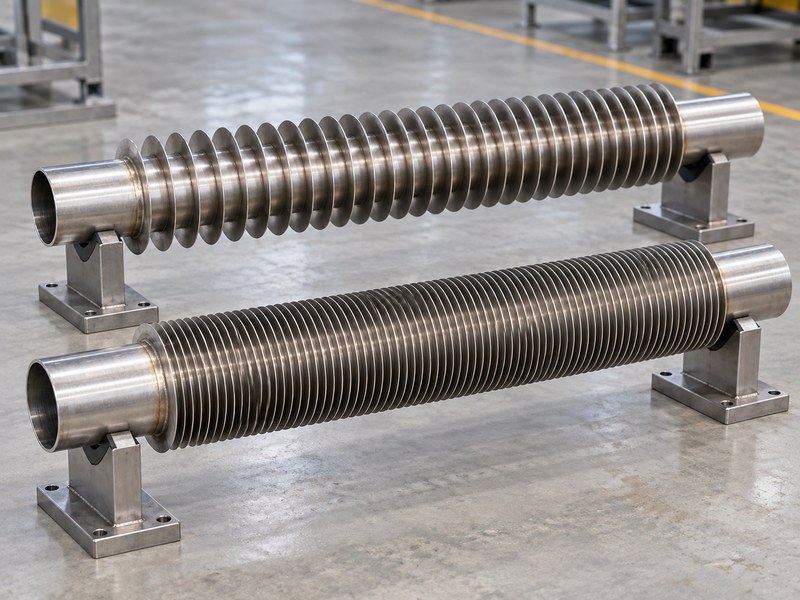
Choose fin pitch and height for a stainless steel finned heat sink using the airflow, available pressure and expected fouling. More fins add surface area but reduce the open passages between them. Tall thin fins also require heat to travel farther from their roots, which can limit how much of the added area is effective.
Include cleaning access in the geometry review
An industrial air stream may carry dust, fibers or other deposits. A pitch that performs well when clean can lose that advantage as material accumulates. Ask how the fin pack will be inspected and cleaned without bending its features.
Compare candidate geometries at the same air-side operating condition. Free-stream velocity, duct velocity and the velocity through narrow fin passages are different quantities, so identify which one appears in a quoted result.
- State the air condition and contamination expected in service.
- Review fin efficiency as well as total area.
- Include maintenance access and acceptable pressure drop.
| Geometry choice | Potential benefit | Tradeoff |
|---|---|---|
| Closer pitch | More area in the envelope | Higher restriction and fouling sensitivity |
| Greater fin height | More exposed area | Longer conduction path |
| Wider passages | Easier access and flow | Less area in the same volume |
Choose the geometry from its installed performance and maintenance needs together.
5. How does the fan affect the heat sink rating?
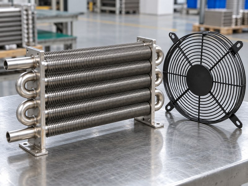
The fan affects a stainless steel finned heat sink rating through the airflow it can deliver against the installed resistance. A free-air fan value does not describe flow through a coil, filter and enclosure. The operating point depends on the fan and system characteristics together.
Review the complete air path
Include guards, filters, duct transitions and nearby obstructions in the airflow assessment. Air can bypass the fin pack if there is an easier route around it. Hot exhaust can also return to the intake and raise the local cooling-air temperature.
Define whether the system must continue operating with a dirty filter or reduced fan capability. Compare the proposed coil and fan arrangement against that condition rather than treating a clean open-bench result as the only design case.
- State the local inlet-air temperature and pressure conditions.
- Control bypass and recirculation around the finned core.
- Record the fan configuration used for qualification.
| Air-path feature | Changes | Review |
|---|---|---|
| Filter or guard | System resistance | Installed operating point |
| Bypass gap | Flow through the core | Duct and sealing arrangement |
| Recirculation | Local inlet temperature | Intake and exhaust separation |
Request the thermal rating with the associated airflow and pressure-drop conditions.
6. How should the finned surface be cleaned?
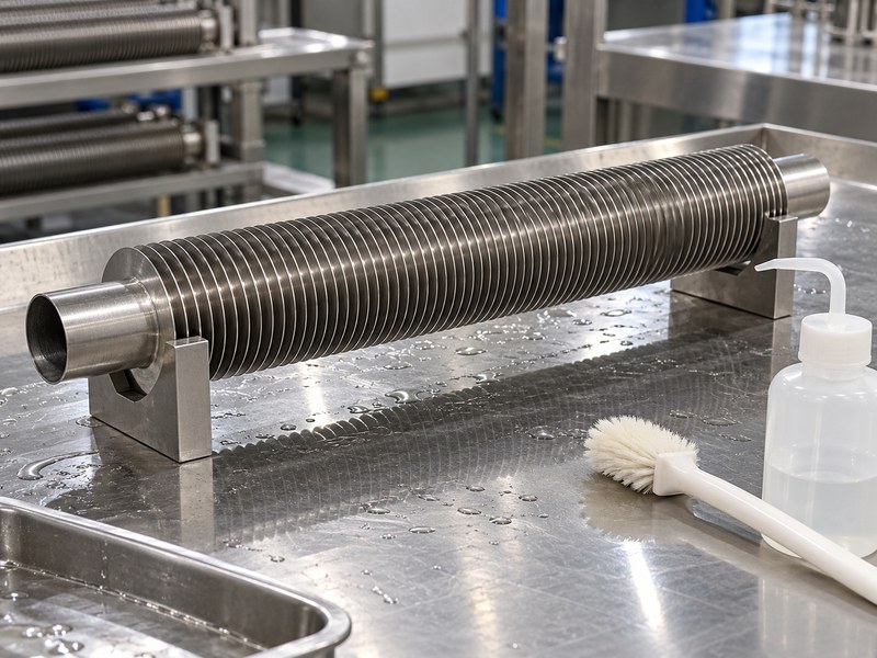
Clean a stainless steel finned heat sink using a method compatible with its materials, fin attachment and deposits. The process must remove contamination without bending fins or damaging joints. Define the cleaning access and drainage before the assembly is enclosed inside equipment.
Preserve geometry during maintenance
Thin fin edges can be damaged by an unsuitable brush or an uncontrolled cleaning jet. A residue-removal method that works on a solid stainless plate may be unsuitable for a closely spaced fin pack. Include the connection materials and any seals in the compatibility review.
Inspect for trapped residue, blocked passages and damaged areas after cleaning. Where service exposure can change corrosion or contact behavior, include the cleaning cycle in qualification rather than testing only a new dry sample.
- Specify approved cleaning agents and application conditions.
- Provide a route for rinse liquid and deposits to leave.
- Define an inspection and replacement criterion for damaged fins.
| Maintenance detail | Purpose | Check |
|---|---|---|
| Access | Reaches the fin pack | No hidden blocked area |
| Compatible process | Preserves materials and joints | Representative cleaning trial |
| Drainage | Removes liquid and residue | Installed orientation |
Keep the maintenance method with the product’s operating specification.
7. How do you define the fluid-side heat duty?
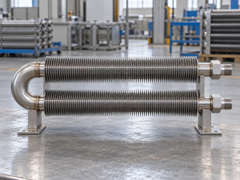
Define the fluid-side duty of a stainless steel finned heat sink using fluid identity, flow and inlet and outlet conditions. For a single-phase liquid, Q = mass flow × specific heat × temperature change provides an energy balance. It does not establish the coil’s air-side capacity by itself.
Use the energy balance as a specification check
For an illustrative water calculation, assume density of 1,000 kg/m³ and specific heat of 4,180 J/(kg·K). A flow of 1 L/min changing by 5 K corresponds to about 350 W. The actual coil must still transfer that heat with its available area, temperature difference and airflow.
Use the properties of the real fluid at the relevant conditions, including any glycol mixture. Condensation or boiling requires a phase-change energy balance rather than relying on the single-phase temperature-change equation alone.
- State the fluid and its operating temperature range.
- Specify flow range and allowable pressure drop.
- Include the connections and pressure-boundary requirements.
| Worked example input | Assumption | Result |
|---|---|---|
| Water flow | 1 L/min | About 0.0167 kg/s |
| Temperature change | 5 K | About 350 W fluid energy change |
| Fluid state | Single-phase liquid | No phase-change term included |
Use this calculation to check the requested duty, then verify that the selected construction can meet it.
8. Where should a finned-tube assembly be supported?
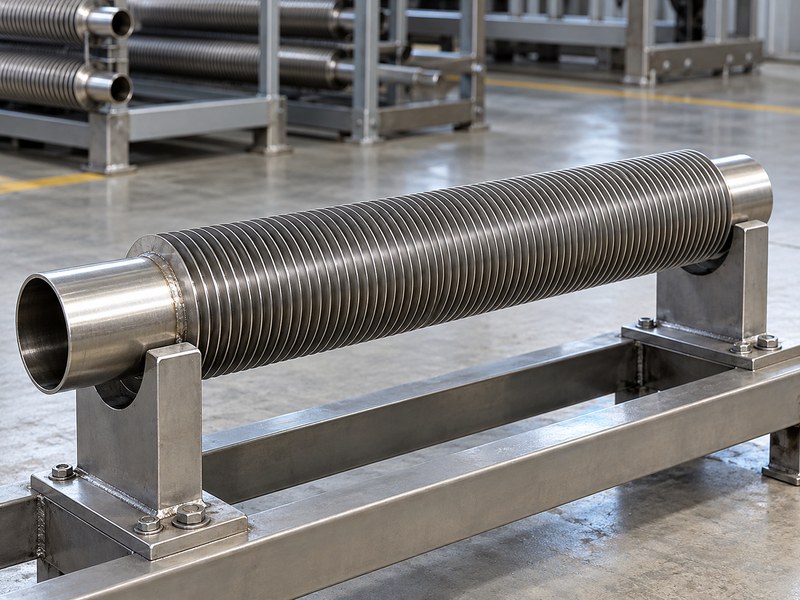
Support a stainless steel finned heat sink through suitable tube, frame or mounting features that can carry the required loads. Thin fins should not become the unintended structural support. Pipe or hose forces also need control so they do not distort the core or overload a connection.
Leave room for thermal movement
The tube circuit and support structure can move as temperatures change. Review fixed and moving points, expansion clearance and the installation sequence. A rigid arrangement that fits at room temperature may place unwanted stress on the tube or its joints during operation.
Use production mounting points during vibration or transport qualification. A test fixture that supports the entire fin pack differently from the installation can miss the loads that matter in service.
- Identify mounting features and permitted connector loads.
- Support external plumbing independently where needed.
- Protect fin geometry during handling and packaging.
| Load source | Suitable review | Avoid |
|---|---|---|
| Core mass | Frame or approved support points | Bearing on thin fins |
| Plumbing | Connector and pipe support | Uncontrolled bending at the tube |
| Temperature change | Expansion and restraint | Locking every point rigidly |
Review supports and connections as part of the supplied assembly.
9. How do you test the installed heat rejection?
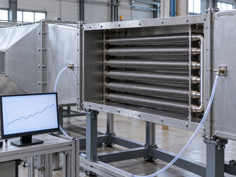
Test a stainless steel finned heat sink using the defined fluid and air conditions, then record heat transfer and pressure drop. The test must represent the intended circuit, orientation and surrounding airflow path. A pressure test and a thermal test establish different characteristics.
Keep the measurements tied to one setup
Record fluid flow, inlet and outlet temperatures and the relevant fluid properties for an energy-balance result. Document air temperature, airflow definition and pressure-measurement locations. Account for other heat paths and measurement uncertainty when checking agreement between the fluid and air sides.
Repeat the required checks after exposure or cycling if those can affect fin contact, leakage or airflow. Keep the leak and pressure acceptance method distinct from the evidence used to support a heat-transfer rating.
- Define stabilization and the accepted measurement method.
- Retain the circuit and airflow configuration with the result.
- Identify whether the reported duty applies to clean or service-exposed hardware.
| Test | Establishes | Conditions to retain |
|---|---|---|
| Thermal | Heat-transfer performance | Fluid and air boundaries |
| Pressure drop | Flow resistance | Flow and measurement locations |
| Leak or pressure qualification | Specified boundary integrity | Approved test requirements |
Accept the rating only with the conditions and construction that produced it.
10. What should the finned heat sink RFQ include?
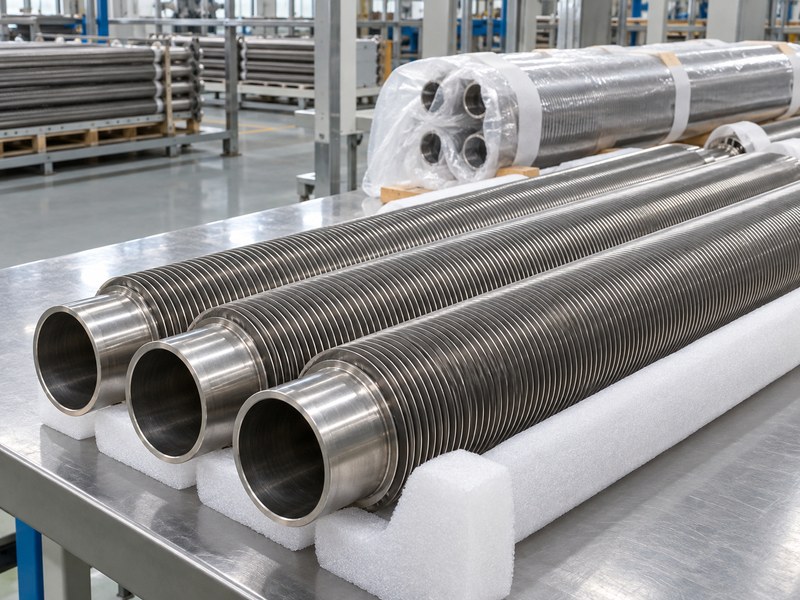
A stainless steel finned heat sink RFQ should contain the construction, materials, fluid duty, air conditions and mechanical constraints. Include the pressure boundary, connection details and cleaning requirements. An outer-size drawing without those conditions cannot support a comparable thermal quotation.
Ask for a complete operating-point proposal
Request the proposed tube circuit, fin attachment, airflow and pressure-drop information. Identify tooling, samples and production inspection separately. Define the conditions for approving material, fin geometry or joining changes after the sample stage.
Share the heat load, fluid circuit and available envelope when you contact us. We can discuss the related heat sink and cold plate interfaces before the system’s heat-rejection arrangement is fixed.
- Provide inlet temperatures, flow ranges and the heat duty.
- Include mounting, plumbing and maintenance access.
- Agree on thermal, leak and production acceptance records.
| RFQ area | Provide | Supplier response |
|---|---|---|
| Thermal duty | Fluid and air operating conditions | Defined-condition rating |
| Construction | Material and connection limits | Proposed circuit and attachment |
| Qualification | Relevant acceptance requirements | Comparable validation plan |
Approve the operating point and construction together with the sample.
FAQ
Q1: Can a finned-tube unit reject heat from a cold plate loop?
Yes, if its capacity, fluid compatibility, flow resistance and operating temperatures suit that loop. Include the pump, cold plate and air-side hardware in the system review.
Q2: Does a wound fin automatically have a welded bond?
No. Winding describes a forming or attachment action, while a welded or other metallurgical bond requires its own joining process. Ask which construction the supplier actually provides.
Q3: Are more fins always better?
No. Added area can increase restriction and fouling sensitivity. Compare the installed heat transfer, fan operating point and cleaning requirements before choosing a closer pitch.
Q4: Can I select stainless without specifying the fluid?
Not reliably. Fluid chemistry, temperature and exposure affect material selection, while fluid properties affect the thermal and pressure-drop calculation. State the real service conditions.
Q5: How do I compare two quoted coil ratings?
Check construction, inlet temperatures, flow definitions, pressure drop and the test configuration. Ratings from different operating points do not establish an equivalent product comparison.