
Choose a stainless steel pin fin heat sink by checking how heat reaches the pins, how air passes between them and why stainless is required. A dense pin array can add weight and restriction without meeting the temperature target. Start with the alloy, source footprint and installed airflow.
1. What is a stainless steel pin fin heat sink?
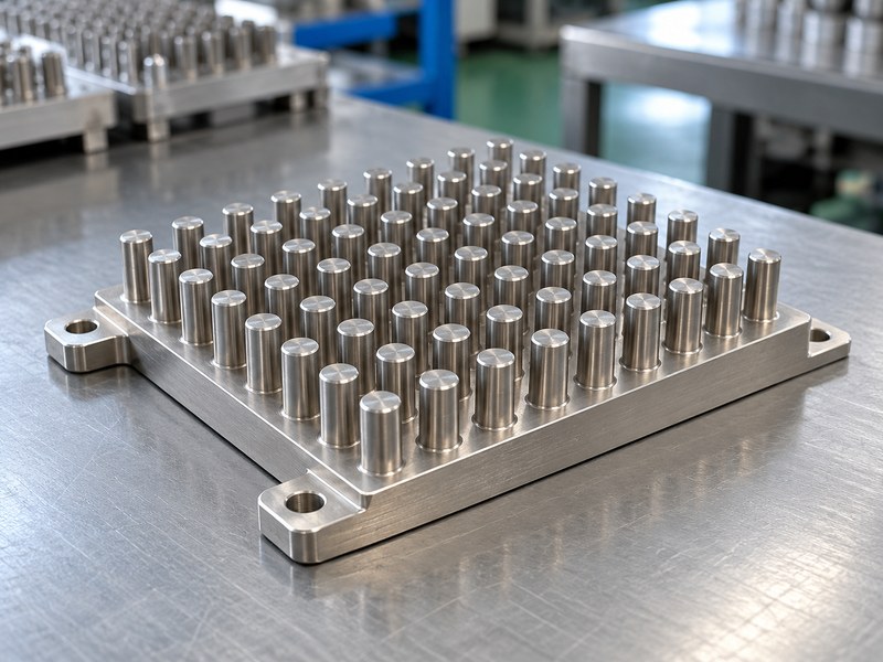
A stainless steel pin fin heat sink has discrete pins connected to a base that receives heat from another part. The pins add exposed area and permit air to move through the array. Their usefulness depends on conduction from the base and the air that reaches each surface.
Define the application before choosing the array
An exposed stainless component may serve a corrosion, cleaning or structural requirement. Its thermal geometry must still work within the available temperature rise. A shape copied from a highly conductive aluminum product can behave differently when made from a different alloy.
Show the source position and the surrounding enclosure in the specification. A concentrated source near one corner can leave part of the pin field cooler and less useful than a simple uniform-base-temperature assumption suggests.
- Identify the heat-source footprint and operating load.
- State why stainless is needed and which surfaces require it.
- Define available space, orientation and airflow access.
| Array element | Function | Check |
|---|---|---|
| Base | Receives and spreads heat | Local temperature gradients |
| Pins | Exchange heat with air | Conduction and airflow |
| Mounting features | Retain the assembly | Contact and structural load |
Specify the complete arrangement rather than selecting a pin count from a photograph.
2. How does stainless conductivity affect the pins?
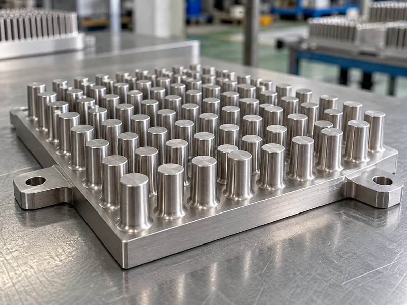
Conductivity affects a stainless steel pin fin heat sink by limiting how closely the pin temperature follows the base temperature. A long thin pin can have a cool tip while the base remains hot. Its full geometric area then contributes less heat transfer than an isothermal-pin calculation predicts.
Use grade-specific properties and a suitable fin model
Confirm the proposed grade and relevant stainless material properties. Stainless families differ, and the operating temperature can affect the design inputs. Use the actual pin cross-section, length and boundary conditions when evaluating fin efficiency.
Shorter or thicker pins can improve conduction along the pin, but those changes also affect mass and open area. They should be assessed with the air path rather than treated as independent improvements.
- Separate base spreading from conduction along the pins.
- Use the specified alloy rather than a generic steel value.
- Check the predicted temperature variation within the array.
| Design input | Affects | Needed review |
|---|---|---|
| Conductivity | Heat reaching the pin surface | Grade and temperature |
| Pin cross-section | Conduction and stiffness | Geometry and airflow |
| Pin length | Area and temperature gradient | Fin efficiency |
Compare the effective heat-transfer area rather than geometric area alone.
3. How should pin pitch and arrangement be chosen?
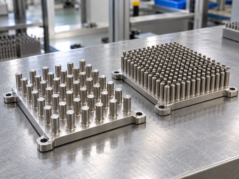
Choose the pitch and arrangement of a stainless steel pin fin heat sink using the available airflow and acceptable restriction. Closely spaced pins create more area within an envelope but narrow the flow passages. In-line and staggered layouts can produce different flow and pressure-drop behavior.
Compare the array at its installed operating point
An array that appears suitable in an open-air model may be restricted by a cover or nearby board. Air can take a bypass route around the pins instead of moving through them. Include those gaps and obstructions when comparing layouts.
For natural convection, orientation and buoyant air paths matter. For forced air, compare the fan and array together. A free-air fan rating is insufficient evidence of the flow through a dense installed pin field.
- State how air enters and leaves the array.
- Compare pressure drop with the intended fan or flow source.
- Include dust or cleaning access where service conditions require it.
| Layout choice | Potential benefit | Tradeoff |
|---|---|---|
| Wider pitch | More open flow passages | Less area in the footprint |
| Closer pitch | More pins and surface | More restriction and cleaning difficulty |
| Staggered arrangement | Different mixing and local flow | Changed pressure drop |
Select the layout from the system result rather than assuming the densest option will cool best.
4. How should stainless and aluminum pin arrays be compared?
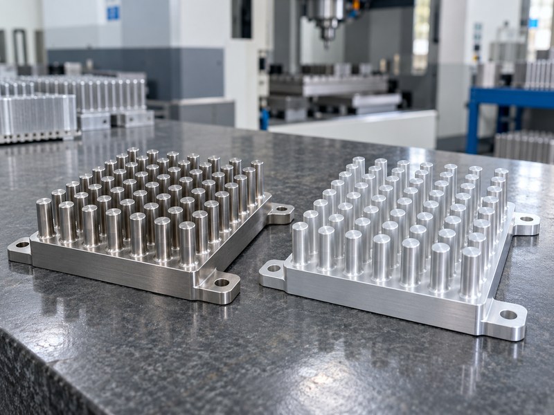
Compare a stainless steel pin fin heat sink with aluminum using identified materials and matched conditions. The comparison can hold geometry constant to study material effects, or allow each material a suitable redesign within the same envelope. State which method was used before drawing a purchasing conclusion.
Account for mass and the complete thermal path
Stainless may be justified by exposure or structure, while aluminum may offer a useful conductive path and lower mass. A hybrid assembly can assign those roles to different parts. It also adds interfaces that must be included in the thermal and environmental review.
Compare the component-temperature target under the same heat load and local air condition. A cooler fin tip can mean that less heat reached that tip, so it should not be treated as proof of a better heat sink.
- Match source footprint, interface and airflow in the baseline.
- Compare installed mass and mounting requirements.
- Allow redesign only within the freedoms specified for both options.
| Comparison | Holds constant | Tells you |
|---|---|---|
| Same pin geometry | Shape and cooling boundary | Material sensitivity |
| Same envelope | Available volume and target | Feasible alternative designs |
| Same assembly duty | All acceptance limits | Practical sourcing choice |
Keep the comparison method and assumptions attached to the result.
5. How much area can the pins use effectively?
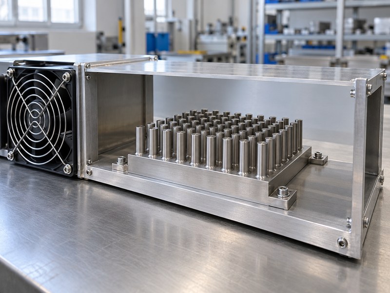
A stainless steel pin fin heat sink uses its area effectively only when the pins remain sufficiently warm and air reaches them. A simplified model can combine exposed base area with fin area multiplied by fin efficiency. Real arrays also have local flow and temperature variations that this model omits.
Work through a bounded example
Assume 0.002 m² of exposed base, 0.010 m² of pin surface and a fin efficiency of 0.5. The effective area in this simplified example is 0.007 m². With an assumed convection coefficient of 15 W/(m²·K) and a 40 K base-to-air difference, the estimate is 4.2 W.
Treating the same pins as uniformly hot would give 7.2 W under those assumptions. Neither number is a product rating; the example shows why fin efficiency changes the area calculation.
- Use a model appropriate to the actual pin geometry.
- Check whether the assumed convection coefficient fits the flow condition.
- Add base spreading, interfaces and other relevant heat-transfer paths.
| Example term | Assumption | Effect |
|---|---|---|
| Exposed base area | 0.002 m² | Directly included |
| Pin area | 0.010 m² | Multiplied by assumed efficiency |
| Pin efficiency | 0.5 | Gives 0.007 m² effective area total |
Validate a selected design using the installed boundary conditions rather than this explanatory estimate.
6. How can stainless pin fins be manufactured?
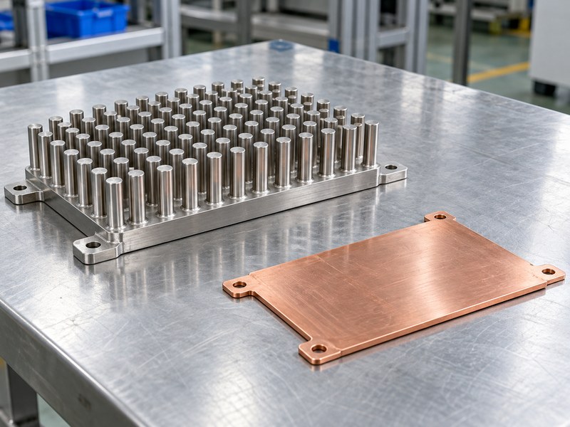
A stainless steel pin fin heat sink needs a manufacturing route suited to its geometry and alloy. A one-piece machined array, an attached-pin assembly and another formed construction have different limits. Ask the supplier to identify the actual route rather than assuming a standard aluminum pin-fin process transfers directly to stainless.
Keep the pin root and final contact face under control
Machining short practical pins can avoid an added pin joint, but material removal, tool reach and access affect cost. An attached-pin route introduces a joint that needs mechanical and thermal review. A proposed forming route needs evidence for the specified stainless material and geometry.
If an additive route is proposed, review the process-dependent properties, contact-face finishing and inspection requirements. A shape that can be represented in a model still needs a repeatable production and verification method.
- Ask how pins are formed and connected to the base.
- Define root geometry, burr control and final surface requirements.
- Include any added joint in thermal qualification.
| Route | Review | Evidence |
|---|---|---|
| One-piece machining | Tool access and practical geometry | Finished-part inspection |
| Attached pins | Joint quality and retention | Thermal and mechanical qualification |
| Other proposed route | Material and process capability | Representative production samples |
Approve the route that produces the required assembly, not merely a visually similar prototype.
7. How should the pin-fin base be mounted?
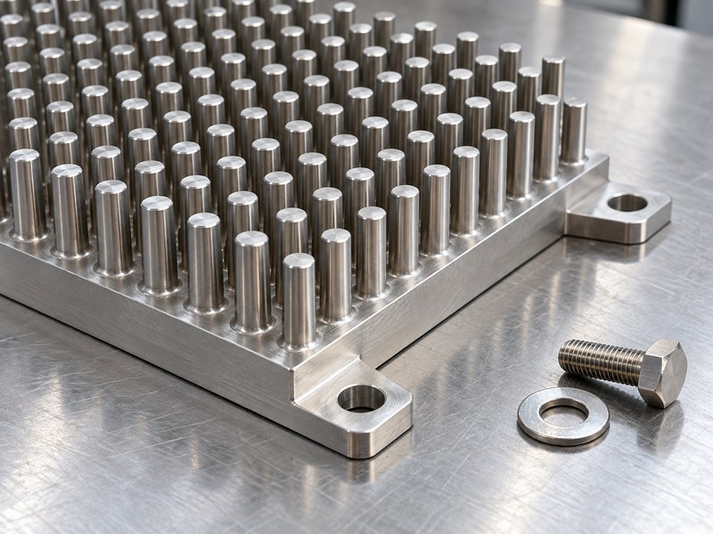
Mount a stainless steel pin fin heat sink through the base or approved mounting features rather than the pins. The interface needs a controlled gap and load. Fasteners also need to respect the package, electrical insulation and service requirements of the complete stack.
Keep retention loads away from fragile surfaces
A pin field can be damaged during installation if tools or clamps press against exposed pins. Provide enough clearance for hardware access, then define an assembly sequence that preserves the interface. Check how the part is supported during transport and maintenance as well as during normal operation.
Choose the interface material using the actual contact condition. A compliant pad can address a designed gap, but it should not become an uncontrolled correction for a bowed base or trapped debris.
- Define the contact face and compressed interface thickness.
- Provide fastener access outside the pin array.
- Review the complete electrical path through screws and supports.
| Mounting detail | Controls | Verify |
|---|---|---|
| Base contact | Interface resistance | Flatness and cleanliness |
| Hardware | Retention and package load | Approved stack and settings |
| Tool access | Installation condition | No pin damage |
Qualify the assembled stack with the hardware and interface intended for production.
8. How do exposure and cleaning affect the array?
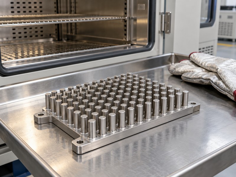
Exposure and cleaning affect a stainless steel pin fin heat sink through deposits, surface condition and access between the pins. Stainless still needs a suitable grade for the environment. A closely spaced array can retain liquid or contamination even when its open outer surfaces look clean.
Design the maintenance route before closing the enclosure
Identify dust, fibers, salts and cleaning chemicals that may reach the part. Review how residue leaves the array and whether an operator can inspect the regions near the base. A cleaning method suitable for a solid plate may bend pins or leave deposits inside a dense field.
Include relevant cleaning and environmental exposure in qualification where they can change airflow, corrosion or the mounting interface. Protect the pins during handling rather than using them as convenient lifting or clamping points.
- State cleaning materials and expected contamination.
- Reserve access for inspection and residue removal.
- Define acceptable damage and the replacement criterion.
| Service condition | Possible effect | Control |
|---|---|---|
| Deposits | Less open flow area | Suitable pitch and maintenance |
| Cleaning liquid | Trapped residue or local exposure | Access and drainage |
| Handling | Bent or damaged pins | Protected contact points |
Evaluate the service-exposed array as well as a clean new sample.
9. How should pin-fin performance be tested?
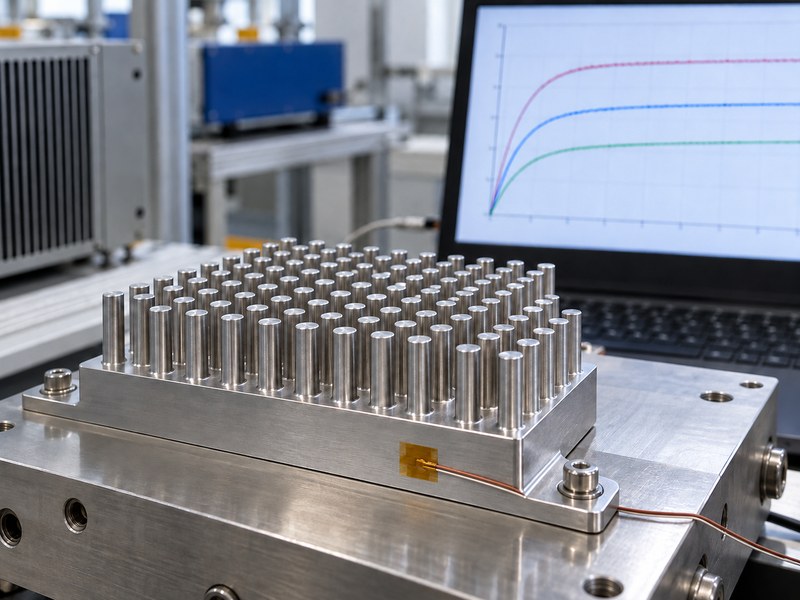
Test a stainless steel pin fin heat sink at a known heat input with documented interfaces, local air conditions and orientation. Measure temperatures where the design criterion applies. A numerical model can help compare options, but its assumed contact and airflow conditions need verification.
Connect each temperature to a physical location
Record base, source and local-air sensor locations, including attachment methods. A sensor near the pin tip answers a different question from one near a concentrated source. Reflective surfaces can also complicate infrared measurements unless emissivity and reflections are handled appropriately.
Calculate the relevant thermal resistance from the measured temperature difference and known heat input. Retain the test setup and repeat assembly if mounting variation could change the comparison.
- Record source footprint and applied power.
- Include the installed fan, cover or duct configuration.
- Check performance after required durability exposure.
| Measurement | Defines | Needed detail |
|---|---|---|
| Source or base temperature | Accepted temperature rise | Sensor location and attachment |
| Local air temperature | Cooling reference | Position near the array |
| Airflow and restriction | Operating boundary | Installed configuration |
Accept the result only for the conditions and construction documented in the test.
10. What should a stainless pin-fin RFQ contain?
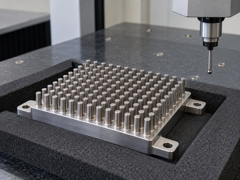
A stainless steel pin fin heat sink RFQ should define the source layout, temperature target, exposure and mechanical interfaces. Include pin and base geometry where fixed, and identify the dimensions that can change. Ask for the production route and its inspection plan before treating a rendered model as an approved design.
Request an operating-condition proposal
Provide heat loss, source footprint, local ambient, available airflow and mounting orientation. Include material traceability, finish, cleaning and packaging requirements where they affect acceptance. Compare supplier proposals against the same temperature and durability limits.
Send your drawing and operating conditions when you contact us. We can review relevant heat sink, mounting and cold plate options while keeping the material requirement and actual cooling duty separate in the design discussion.
- Define the accepted material and substitution policy.
- Ask for geometry and manufacturing constraints to be identified.
- Agree on sample validation and production checks.
| RFQ area | Include | Supplier response |
|---|---|---|
| Thermal | Load, source and airflow boundary | Proposed validation conditions |
| Mechanical | Envelope, mounting and pin protection | Manufacturability review |
| Quality | Material and inspection requirements | Comparable evidence package |
Approve the production route and test configuration with the final sample.
FAQ
Q1: Are stainless pin fins automatically better for harsh environments?
No. Grade, geometry, deposits and cleaning conditions determine suitability. Define the actual exposure and qualify the finished assembly rather than relying on the word stainless alone.
Q2: Do taller pins always improve cooling?
No. Taller pins add area but require heat to travel farther from the base. Check fin efficiency, airflow and mounting space before increasing their height.
Q3: Can I copy an aluminum pin-fin design in stainless?
Only after reviewing material properties, mass, production capability and thermal performance. An identical outline is useful for comparison but does not establish an equally suitable production design.
Q4: How do I know whether the quoted rating applies?
Check heat-source size, interface, orientation and local airflow conditions. A rating from a different fixture or cooling boundary may not describe your installation.
Q5: Can I use a cold plate if the pin array cannot meet the target?
Yes, if the system can support the required liquid circuit. Review inlet conditions, flow, pressure drop, compatibility and service access together with the new source-temperature target.