
Choose a surface treated radiator heat sink by comparing device temperatures under controlled conditions, not by comparing colors or camera images alone. Two samples can produce different infrared readings even when their true temperatures match. A thicker contact coating can also offset a useful change on the exposed fins. You need a test that separates those effects before approving a finish change.
This guide explains how to evaluate a surface treated radiator heat sink with the same geometry, interface, heat input and cooling conditions. It focuses on the thermal comparison. Finish chemistry, corrosion protection and dimensional acceptance still need their own requirements, because one temperature test cannot answer every purchasing or reliability question.
1. What should a surface treated radiator heat sink test prove?
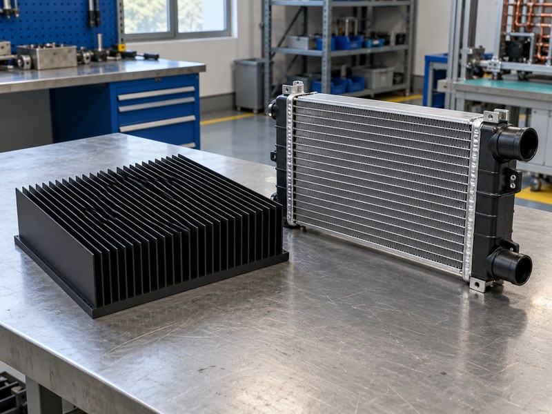
A surface treated radiator heat sink test should establish whether a specified finished assembly meets its temperature limits at defined operating conditions. State which component you are testing. A direct-air finned cooler receives heat through its base, while a liquid radiator receives heat from coolant. The surface finish may affect both, but their thermal boundaries and useful measurements differ.
Which question should the comparison answer?
Decide whether you are qualifying the complete finished part or investigating one coating effect. Qualification uses the production arrangement and its acceptance limits. An investigation needs tighter control of variables so a changed interface or altered airflow does not explain the result. Write the question and the measurement location before you run the test, then keep the test report tied to that scope.
- Identify the supplied component and assembly revision.
- State the operating point and temperature limit.
- Separate qualification from coating research.
| Test purpose | Evidence needed |
|---|---|
| Assembly qualification | Temperatures against defined limits |
| Finish comparison | Controlled geometry and boundary conditions |
| Measurement review | Sensor method and uncertainty |
A test becomes useful when its result answers a defined engineering question.
2. Does a darker finish always improve cooling?
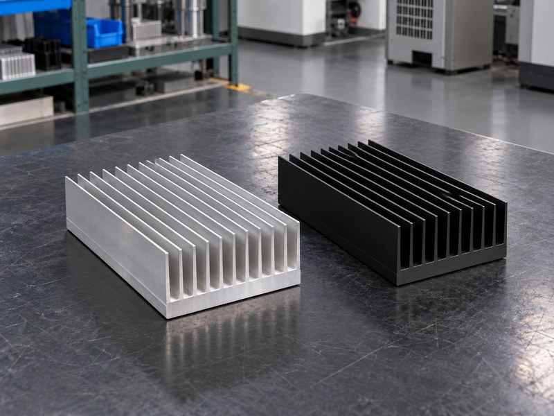
A darker surface treated radiator heat sink does not automatically run cooler in every installation. Visible color is only one surface characteristic, and cooling also depends on conduction, convection and thermal radiation. A finish can change infrared emissivity, but the assembly must have a useful radiative path to cooler surroundings for that change to matter. Nearby warm walls and crowded fins alter that path.
What should you ask about a claimed benefit?
Ask where the finish was applied and how the comparison was performed. A test in still air may give a different result from one with strong forced airflow. A comparison between different geometries cannot isolate a finish effect. Also check whether the reported value is a device temperature, a base temperature or a camera reading corrected for the particular surface.
- Compare the same cooler geometry.
- Describe the surrounding surfaces and air conditions.
- Identify the actual measured temperature.
| Claim | Question to resolve |
|---|---|
| A darker part runs cooler | Under which airflow and surroundings? |
| Radiation increased | What surface and measurement support that result? |
| Device temperature fell | Were interface and power unchanged? |
Treat a general color claim as a question for the test plan.
3. How can a coating add contact resistance?
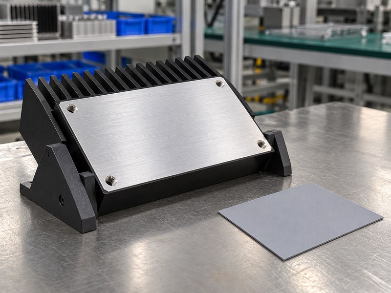
A surface treated radiator heat sink can gain resistance when a coating lies between the device and the cooler. For an ideal uniform layer, through-thickness resistance equals thickness divided by conductivity and contact area. That model excludes roughness, imperfect contact and spreading. Use it to understand sensitivity, then obtain material and interface data appropriate to the actual pressure and temperature.
What does an illustrative layer calculation show?
Assume a layer is 50 micrometers thick, its conductivity is 0.25 W/m·K and its contact area is 400 square millimeters. The ideal layer resistance is 0.50 K/W, which would add 20 K at 40 W if the entire heat flow crossed that layer. These assumed values explain the model; they do not describe a particular finish. The production thermal pad and the remaining interfaces must be evaluated separately.
- Identify whether heat crosses the coating.
- Use consistent units in the calculation.
- Keep contact resistance separate from bulk layer resistance.
| Assumed parameter | Illustrative value |
|---|---|
| Layer thickness | 50 micrometers |
| Layer conductivity | 0.25 W/m·K |
| Ideal layer resistance | 0.50 K/W |
Use this calculation to identify which interface deserves a measured comparison.
4. Why must airflow stay the same?
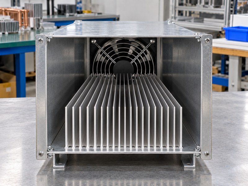
Hold airflow constant when comparing a surface treated radiator heat sink finish, because a small installation change can alter the cooling result. A fan’s free-air rating does not tell you how much air passes through the fin channels. Duct gaps, filters and outlet restrictions determine the installed flow. A changed cable route or shroud position can therefore complicate a coating comparison.
Which setup details should be recorded?
Keep the duct, fan setting, cooler position and inlet measurement location consistent between samples. Record any fixture that blocks a passage or changes leakage around the fins. For natural convection, preserve orientation and clearance around the part. Allow the room or chamber to stabilize after moving equipment, and check whether warm exhaust returns to the inlet during a long test.
- Keep fin channels and duct geometry unchanged.
- Measure inlet air near the cooler.
- Record orientation and nearby obstructions.
| Controlled detail | Reason |
|---|---|
| Duct and shroud | Determines useful flow through fins |
| Local inlet temperature | Sets available temperature rise |
| Mounting orientation | Affects natural convection |
Repeat a suspicious result after checking the airflow arrangement before changing the coating specification.
5. How do you establish a thermal resistance result?
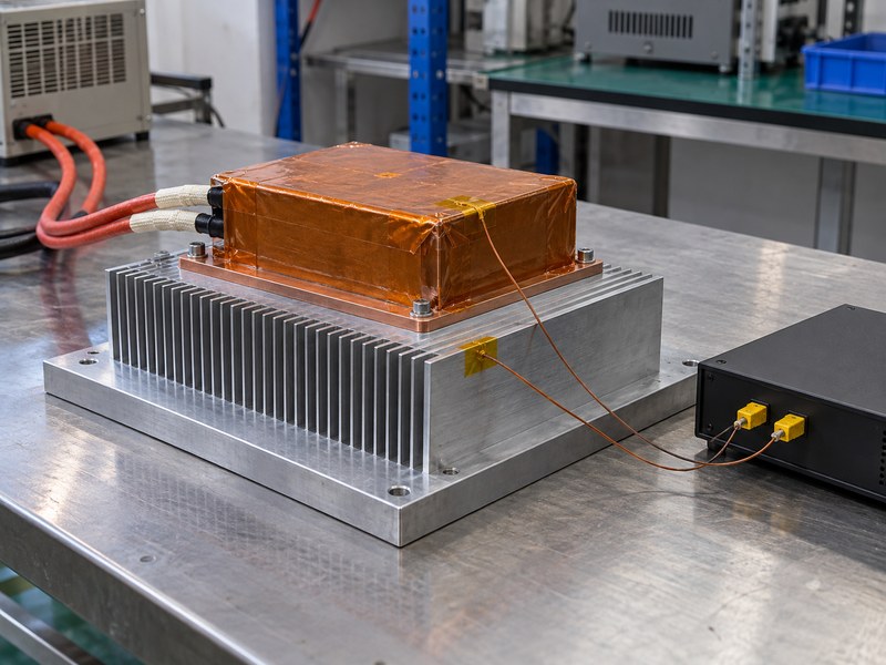
Measure a surface treated radiator heat sink resistance from a clearly defined temperature difference divided by heat flow at steady conditions. Identify whether the temperature belongs to the case, the base or another point. A base-to-air result cannot automatically replace a device junction-to-air value. The correct interpretation depends on the heat path and on what the sensors actually measured.
What must be included with the number?
For an illustrative test, a 30 K base rise at 30 W corresponds to 1 K/W from that measurement point to the stated air location. The result only describes that setup. Record the applied power and account for relevant heat that bypasses the intended path through leads or fixtures. Explain how steady operation was defined rather than selecting a convenient moment from a changing temperature trace.
- Name the two temperature locations.
- Record power independently of temperature.
- Define the steady-state acceptance condition.
| Reported item | Required context |
|---|---|
| Temperature difference | Sensor locations and reference air |
| Heat input | Electrical measurement and relevant losses |
| Resistance | Operating conditions and steady-state definition |
Retain the underlying readings so the resistance calculation can be checked.
6. How can surface finish mislead infrared measurement?
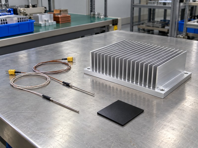
An infrared camera can misread a surface treated radiator heat sink if its emissivity and reflected-temperature assumptions do not fit the surface. Shiny metal can reflect radiation from surrounding objects. A matte coating may produce a more stable image while the actual device temperature remains unchanged. Do not interpret a color map as proof that one cooling assembly performs better.
Which independent check helps?
Use a suitable contact measurement or another validated method at a defined location. Keep the sensor attachment and its influence on the surface consistent. Review semiconductor thermal measurement guidance before converting a package surface reading into an estimated junction temperature. The equipment’s measurement procedure should also address calibration, reflected surroundings and uncertainty where small temperature differences drive the decision.
- Use surface-appropriate camera settings.
- Check a defined point with an independent method.
- Document attachment and uncertainty.
| Observation | Possible explanation |
|---|---|
| Different camera temperatures | Different surface emission or reflection |
| A bright reflected patch | Radiation from nearby surroundings |
| Sensor disagreement | Placement, attachment or calibration difference |
Resolve the measurement discrepancy before ranking the finishes.
7. Which mechanical variables should remain fixed?
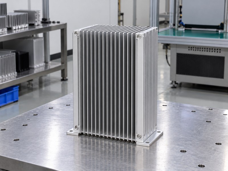
Keep the mounting joint fixed when comparing a surface treated radiator heat sink. Changes in torque, clamp position, pad compression or base flatness can alter thermal contact. If finishing distorts the contact face or leaves residue on a masked pad, the finished component may differ mechanically from the original sample. Inspect those features rather than assuming a shared part number means an identical interface.
How should samples be assembled?
Use the intended heat sink mounting hardware and a documented tightening or clamping method. Record the interface material and replace it when its use conditions require replacement. If you disassemble a sample between tests, consider whether the joint remains comparable. A repeat assembly check can show whether normal mounting variation is larger than the finish effect you are trying to measure.
- Check contact-face condition and flatness.
- Control clamp location and assembly method.
- Track the interface material used for each run.
| Joint variable | Useful control |
|---|---|
| Clamp force | Defined fastening or spring arrangement |
| Interface material | Identified material and compressed condition |
| Contact geometry | Inspection of the finished face |
Include normal assembly variation when deciding whether an observed difference is meaningful.
8. How do you compare results across operating points?
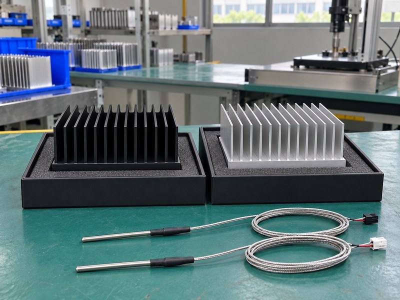
Compare a surface treated radiator heat sink across operating points that represent its intended service. A finish difference at one power level may not persist at another temperature or airflow. Include the condition that is likely to produce the highest device temperature, along with relevant normal operation. Keep the comparison matrix small enough that each result can be traced to a controlled setup.
Which repeat runs are useful?
Repeat the reference configuration often enough to notice drift in the rig or ambient conditions. If two finishes produce a small difference, consider sample and assembly variation before attributing the result to the surface. Report the observed range and the measurement uncertainty. Avoid quoting a universal improvement percentage from a single sample pair tested at one point.
- Include the limiting operating condition.
- Repeat a reference configuration.
- Separate sample variation from measurement uncertainty.
| Comparison | Purpose |
|---|---|
| Same finish, repeated assembly | Checks mounting repeatability |
| Reference run over time | Detects setup drift |
| Multiple relevant loads | Tests the operating envelope |
Base the finish decision on the range your equipment must handle.
9. What changes for a liquid-cooled assembly?
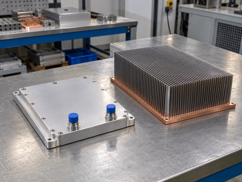
A surface treated radiator heat sink used with liquid cooling needs separate source-side and heat-rejection measurements. The cold plate moves heat into coolant, while a radiator can reject it to air. An external finish on either part does not establish the condition or compatibility of wetted passages. Measure flow and coolant inlet conditions alongside device temperature when comparing the assembly.
Which supplier data remain necessary?
A hybrid liquid-cooled heat sink may combine several heat paths. Define which path the test result covers and whether the supplied part includes the rest of the cooling loop. Keep fluid, concentration and temperature consistent. Review changes to ports, seals and internal finishes separately, because a successful temperature comparison does not establish leak integrity or long-term fluid compatibility.
- Identify device, coolant and ambient boundaries.
- Record flow and fluid identity.
- Keep thermal and containment acceptance separate.
| Boundary | Measurement or requirement |
|---|---|
| Device to cold plate | Interface and device temperature |
| Coolant circuit | Flow and inlet temperature |
| Radiator to air | Air conditions and heat rejection |
Use a complete boundary diagram when more than one supplier provides the cooling components.
10. What should the approval record contain?
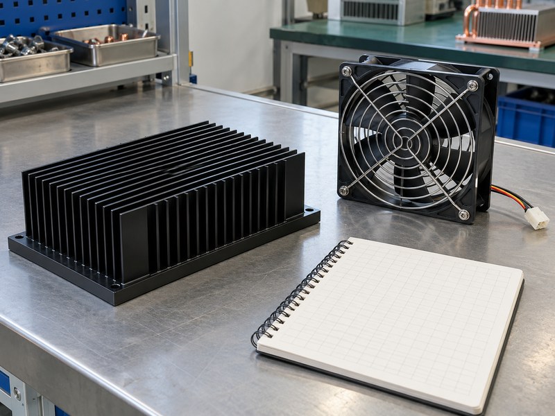
Approve a surface treated radiator heat sink with a record that connects the finish, assembly and measured result. Include part revisions, sensor positions, power, inlet conditions and the acceptance limits. Keep the original readings with the calculation. A summary temperature without its setup cannot guide a later supplier change or explain why a replacement part behaves differently in service.
How do you control later changes?
List which changes require engineering review, such as a different finish process, altered masking or a new interface material. Define the affected checks instead of automatically repeating every test. Retain the accepted sample identity and production inspection requirements. This gives a service or purchasing team a clear way to determine whether a proposed replacement matches the configuration that was approved.
- Link results to part and finish revisions.
- Record assumptions and measurement limits.
- Define review triggers for later substitutions.
| Approval record | What it preserves |
|---|---|
| Setup and conditions | Meaning of the thermal result |
| Part and assembly identity | Reproducibility |
| Change requirements | Control of replacement configurations |
Share your test conditions and drawing when you contact us for a prototype review.
Frequently asked questions
Q1: Can I compare black and silver parts using one camera setting?
Only if the measurement method supports that comparison. Different surface emission and reflection can change the apparent temperature.
Q2: What’s the best temperature to report?
Report the temperature tied to your acceptance limit and identify its location. Include base, air or coolant readings when they explain the heat path.
Q3: How do I know if a small temperature difference is real?
Compare it with measurement uncertainty and repeatability. Repeat assembly and reference runs before attributing a small change to the finish.
Q4: Can a finish raise the device temperature?
Yes. A layer across the contact path, poor masking or changed flatness can add resistance even when external surfaces have a useful finish.
Q5: Does one passing test qualify every operating condition?
No. Test the required load, air or coolant conditions, and the relevant installation arrangements defined by your application.