
Choose a tubular heat sink by matching its contact geometry, fin arrangement and installed airflow to your heat load. A round outline alone cannot establish cooling performance. If a cylindrical housing leaves little space around a hot component, a finned tube may fit the package while still failing at the contact interface or air path. Start a custom tubular heat sink review with the complete assembly, including the source footprint, mounting details and temperature limits.
1. What is a tubular heat sink?
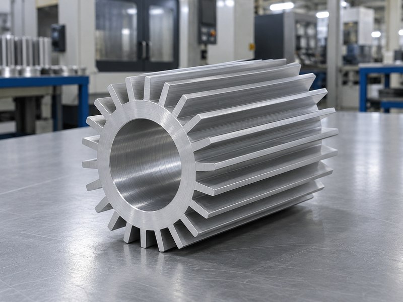
A tubular heat sink is a heat-dissipating component with a tube-like body or a thermal assembly described by that shape. The name does not define a universal cross-section. One design may have an open bore with external fins, while another uses a different core or an assembled structure. Ask for a drawing before assuming what carries heat, what supports the part or whether any passage contains coolant.
Which geometry does the drawing describe?
For the hollow finned profile discussed here, a continuous annular hub connects the external fins around an axial opening. Heat must enter that hub through an actual contact surface, then spread into the fin field. The bore may provide clearance or accommodate a cylindrical interface, but those functions require separate specifications. An open cavity is not automatically a useful cooling channel, a heat pipe or a qualified pressure boundary.
- Identify the heat-contact surface and the open passage.
- Define the complete outer envelope, including fin tips.
- State whether the design is dry or fluid-wetted.
| Drawing feature | Question to answer |
|---|---|
| Annular hub | Where does heat enter the metal? |
| Axial bore | Clearance, contact interface or specified flow path? |
| External fins | Which surfaces reach the installed airflow? |
Key takeaway: specify the cross-section and heat path before selecting a tubular form.
2. Is a tubular heat sink the same as a heat pipe?
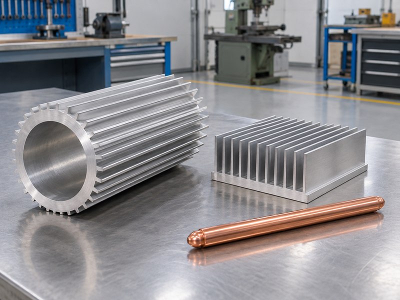
A tubular heat sink is not necessarily a heat pipe. A plain aluminum finned tube transfers energy through its metal structure, then rejects heat through exposed surfaces. A heat pipe uses a sealed working-fluid system to transport energy between regions. Its tube-like appearance does not establish the operating limits, internal construction or performance of a different tubular component.
What evidence identifies the cooling mechanism?
Ask the supplier to describe the heat-transfer architecture in the quotation. For a dry finned profile, review conduction, spreading and air-side rejection. For a two-phase device, request the relevant capacity and operating-condition information from the device supplier. A heat pipe heat sink can combine transport and fin-based rejection, but that assembly still needs a defined interface and an adequate final air path.
- Separate the body shape from the cooling mechanism.
- Identify every interface between the source and fins.
- Request operating limits for any integrated thermal device.
| Component type | What needs confirmation |
|---|---|
| Dry finned tube | Metal path, contact and air-side rejection |
| Heat pipe assembly | Device capacity and installation conditions |
| Liquid-cooled assembly | Flow path, seals and fluid compatibility |
Key takeaway: similar external shapes can serve different thermal architectures.
3. How does heat enter a tubular heat sink?
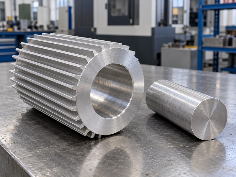
Heat enters a tubular heat sink through the surfaces that physically contact the source or an intermediate spreader. An air gap through the centre of a hollow profile cannot conduct heat like a solid base. Match the contact design to the source footprint. Depending on the assembly, that may require a controlled cylindrical fit, an annular contact face or a separately reviewed adapter.
Where can a round assembly lose thermal contact?
Check the tolerance stack and mounting force rather than comparing nominal diameters alone. A bore interface may need a defined fit and interface material; an end-face interface needs suitable flatness and alignment. A small central heat source may also need a spreader before its heat can reach the annular hub. Discuss these features alongside the available thermal interface materials, including the compressed gap and the material’s installation requirements.
- Map the actual source footprint onto the contact surface.
- Resolve the contact geometry before using a thick pad to fill a gap.
- Check the finished surfaces after coating and cleaning.
| Interface | Review focus |
|---|---|
| Cylindrical bore contact | Fit, contact extent and assembly method |
| Annular end face | Flatness, alignment and usable contact area |
| Adapter or spreader | Added thermal resistance and mounting stack |
Key takeaway: the contact design must connect the source to the annular metal structure.
4. Which airflow suits a tubular heat sink?
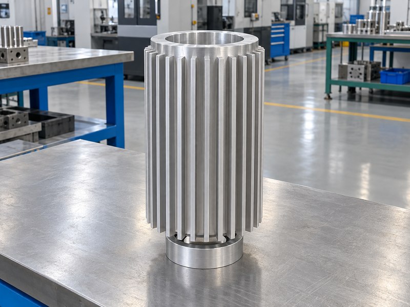
A tubular heat sink needs airflow that can reach its fin surfaces and carry heated air away. Longitudinal fins create channels along the tube, while other fin arrangements create different flow paths. Natural convection depends on installation orientation and surrounding clearance. Forced convection also depends on the fan’s operating point and the resistance of the installed system.
What should you check inside the enclosure?
A fan aimed at the central opening may bypass much of the external fin field, depending on the shroud and flow distribution. A nearby cover can also obstruct the channel exits even when the bare part looks open on a bench. For passive cooling, assess buoyant flow under the actual mounting orientation. Use an assembly-level model or test to compare options; neither the fin count nor the fan’s free-air rating proves the available cooling in the product.
- Keep inlet and outlet restrictions in the review.
- Check for bypass around the surfaces that reject heat.
- Test the intended orientation and enclosure arrangement.
| Operating condition | Information needed |
|---|---|
| Natural convection | Orientation, clearance and temperature rise |
| Forced convection | Installed flow and system resistance |
| Enclosed installation | Inlet, outlet and recirculation paths |
Key takeaway: validate the airflow that reaches the fins, not the airflow suggested by appearance.
5. How should you size a tubular heat sink?
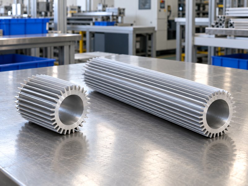
Size a tubular heat sink around the allowable thermal resistance, source footprint and available installation space. Outer diameter, bore size, hub wall, fin height and length influence different parts of that calculation. More metal can support spreading or transient storage, but added mass alone does not establish continued cooling. The finished geometry must fit both the heat path and the airflow.
What does a temperature budget tell you?
As an illustrative screening calculation, a 60 W heat input with a permitted 30 K rise allows 0.50 K/W across the thermal path being evaluated. If that budget starts at the device junction, account for package and interface contributions before assigning the remaining resistance to the sink. Keep sensor locations and temperature definitions consistent during validation. A measured housing temperature, a calculated junction temperature and a fin-tip temperature should not be treated as interchangeable evidence for the same limit.
- Define continuous and transient heat loads.
- State which temperature locations define the budget.
- Reserve the required space for mounting and airflow.
| Illustrative input | Value or meaning |
|---|---|
| Heat input | 60 W |
| Permitted rise | 30 K across the stated path |
| Resistance budget | 0.50 K/W before allocating its components |
Key takeaway: translate the temperature limit into a defined thermal-path budget before choosing dimensions.
6. Which material fits a tubular heat sink?
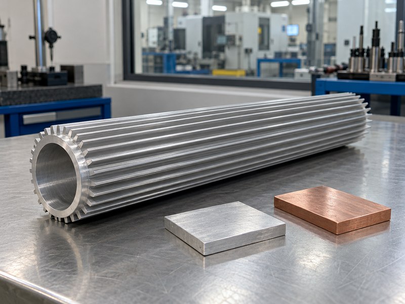
Choose a tubular heat sink material using the required conductivity, strength, weight, manufacturing route and surface treatment. Aluminum extrusions can suit a constant cross-section, while other requirements may justify machining or an assembled design. Specify the alloy and temper rather than accepting a generic aluminum description. A material change can affect both thermal calculations and the finished appearance.
When does a material comparison become useful?
A more conductive metal may add weight, cost or fabrication constraints without resolving a poor contact or air path. For a long hollow profile, material condition and wall geometry also influence handling and machining stability. Review an extruded heat sink route against the actual cross-section and required quantity. Ask for traceable material records and a sample that represents the production stock, particularly when a prototype comes from a different form of material.
- Define alloy, temper and stock form on the drawing.
- Compare total assembly weight and mounting requirements.
- Recheck affected requirements after any substitution.
| Selection factor | Why it belongs in the review |
|---|---|
| Conductivity | Affects the metal heat-spreading path |
| Strength and condition | Affect support and manufacturing choices |
| Finish response | Can change cosmetic and coating results |
Key takeaway: select a material within the complete manufacturing and thermal design.
7. How should a tubular heat sink be mounted?
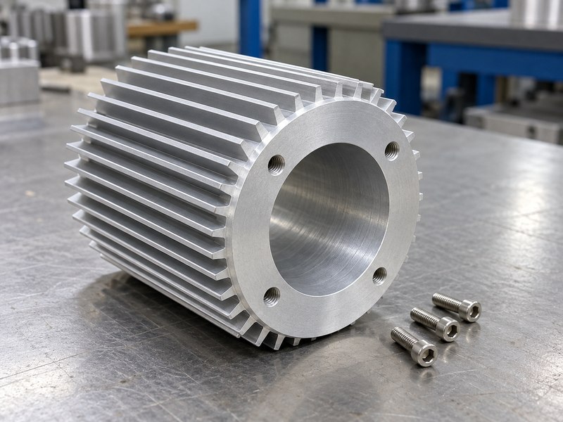
A tubular heat sink should be supported through defined structural surfaces without crushing or bending its fins. Its attachment also needs to maintain the intended thermal interface. Review the load path, fastening access and any vibration requirements. A hollow wall or a thin fin should not become an unreviewed clamping feature merely because it is convenient to reach.
Which mounting details need the assembly model?
Check whether screw tightening can distort a thin annular face or change a bore fit. Define suitable stops or supports if the assembly requires controlled compression. With heat sink mounting hardware, coordinate fasteners, installation sequence and the supported component’s limits. A fastening arrangement that works for a solid block may need a different review when the load passes through a hollow cylindrical body.
- Identify structural datums and supported surfaces.
- Keep clamp loads away from delicate fin tips.
- Review tightening access and assembly sequence.
| Mounting detail | Check |
|---|---|
| Support location | Carries the specified assembly loads |
| Fastener arrangement | Maintains fit and contact alignment |
| Installation access | Allows repeatable assembly without fin damage |
Key takeaway: support the part and control the contact interface through the same assembly review.
8. Which finish belongs on a tubular heat sink?
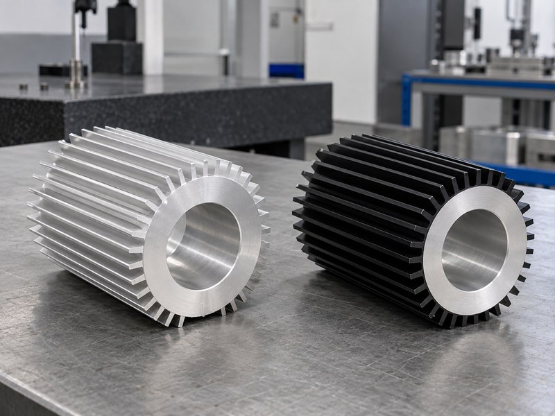
A tubular heat sink finish should meet the application’s environmental, cosmetic and interface requirements. Anodizing or another treatment can change appearance and surface behaviour, but it does not establish a universal cooling improvement. Define which surfaces receive the treatment and which remain protected. Review coating effects on bore fits, threads, contact faces and any electrical bonding locations.
How should you evaluate a proposed finish?
The Aluminum Anodizers Council explains that the underlying mechanical texture remains relevant to the anodized appearance. For thermal performance, compare the finished assembly under the intended conditions. Keep electrical insulation requirements separate from a cosmetic anodizing note; the product needs the applicable design and qualification evidence. Also ask how masking, cleaning and packing preserve the controlled surfaces through delivery and installation.
- Define coating and masking on named surfaces.
- Check finished dimensions at functional interfaces.
- Approve the final color and texture reference.
| Surface | Requirement to coordinate |
|---|---|
| External fins | Environmental and cosmetic treatment |
| Contact face or bore | Specified interface condition |
| Bonding point | Approved electrical contact requirement |
Key takeaway: specify a finish as part of the functional component, not a color choice alone.
9. How do you validate a tubular heat sink?
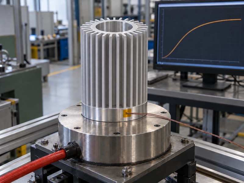
Validate a tubular heat sink using a finished sample and a documented test arrangement that represents the installation. Record power input, ambient or inlet temperature, mounting method, interface material and sensor locations. The measured thermal path must match the design budget. Testing a bare sample in open air cannot automatically qualify a restricted enclosure installation.
Which records make a result usable?
Retain the tested drawing revision and the fixture configuration alongside the temperature data. For forced air, define the relevant flow condition and restrictions; for passive cooling, define orientation and surroundings. Note the criterion used to judge whether temperatures have stabilised. If a simulation helps select the design, compare its assumptions with the physical setup rather than treating a contour plot as a test report.
- Identify the exact finished configuration tested.
- Separate measured results from estimates or illustrations.
- Revalidate the requirements affected by a change.
| Validation record | What it establishes |
|---|---|
| Configuration | Geometry, finish and mounting condition |
| Boundary conditions | Heat input and heat-rejection environment |
| Measurements | Temperatures at defined locations and times |
Key takeaway: accept a thermal result together with the conditions that produced it.
10. What should a tubular heat sink enquiry include?
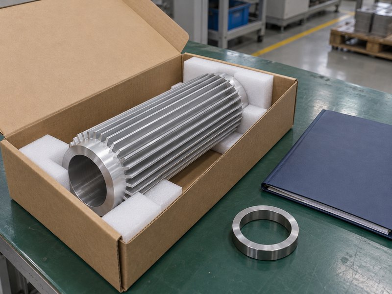
A tubular heat sink enquiry should connect the drawing, source interface, heat load and purchasing quantity. Include the bore’s purpose and any functional surfaces that need machining or protection. Separate sample quantity from expected repeat demand. Ask the supplier to identify open requirements before quoting so manufacturing assumptions do not become surprises during sample approval.
What closes the design review?
Use the sample stage to confirm dimensions, assembly fit, finish and the required thermal evidence. Record the proposed production route and any differences from the prototype. Packaging should protect both the fin field and contact surfaces. To discuss a custom component, contact us with the source footprint, available space, mounting arrangement and air or coolant conditions.
- Supply a model and drawing with consistent revisions.
- State the temperature target and operating conditions.
- Agree inspection, packaging and change-control records.
| Enquiry item | Include |
|---|---|
| Geometry | Bore, contact surfaces and installation envelope |
| Thermal brief | Heat input, temperatures and rejection conditions |
| Supply plan | Sample quantity, forecast and release evidence |
Key takeaway: quote the complete thermal component and its acceptance requirements.
Frequently asked questions
Q1: Can I assume all tubular heat sinks contain fluid?
No. The description may refer only to shape. Confirm the actual cross-section and whether the component is dry, liquid-cooled or a two-phase assembly.
Q2: Is the central bore automatically a useful air duct?
No. It needs a defined flow path and a reason to participate in heat rejection. Air passing through the bore may bypass the outer fins.
Q3: Can I mount a central LED directly over an open bore?
Only with a reviewed contact and support design. An open cavity cannot replace the solid thermal path needed beneath the source.
Q4: Should I choose the longest profile that fits?
Compare the complete thermal and airflow result. Extra length can change weight, access and flow distribution without providing the required benefit.
Q5: How do I know whether the supplier’s rating applies?
Compare its tested geometry, interface, orientation and air conditions with your installation. Request clarification wherever the thermal path or measurement locations differ.