
Choose a wear resistant radiator heat sink by matching its thermal resistance, exposed surfaces and mounting details to your equipment. A scratched fin block may still cool adequately, while a damaged contact face can raise device temperature. Define where wear occurs before choosing a harder finish or changing the cooling architecture.
1. What makes a wear resistant radiator heat sink suitable?
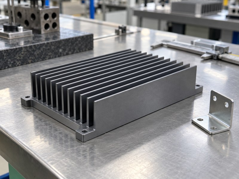
A suitable wear resistant radiator heat sink meets both the temperature limit and the mechanical conditions of service. In an industrial drive, those conditions can include handling during installation, vibration at the bracket and dust around the air inlet. Treat each exposure separately. Abrasion, impact and corrosion produce different damage and need different acceptance criteria.
Where does the part experience contact?
Start with the contact points. A protective finish on exposed aluminum can reduce surface wear, but it cannot stop a thin fin from bending under a dropped tool. Repeated rubbing at a mounting rail may need a replaceable wear strip or a different bracket. Keep rubbing away from the device contact face, which must remain stable through assembly and servicing. You can often protect that face with packaging and a defined assembly sequence before changing the metal itself.
- Mark handling surfaces, mounting rails and exposed fin edges.
- Identify contaminants, cleaning tools and service intervals.
- Separate cosmetic marks from damage that affects function.
Specify the damage that would cause rejection.
| Exposure | Design response | Acceptance check |
|---|---|---|
| Handling scratches | Protect exposed faces | Agreed visual sample |
| Repeated rubbing | Isolate the contact path | Representative wear test |
| Fin impact | Add clearance or protection | Fin position and airflow |
Use this distinction when reviewing a supplier’s proposed finish.
2. How should you calculate the thermal resistance target?
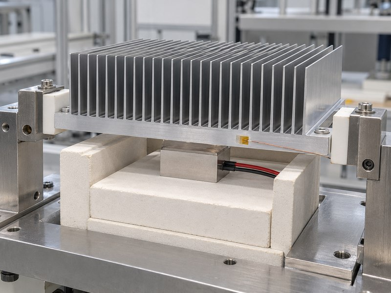
Calculate the wear resistant radiator heat sink target from the allowable temperature rise divided by dissipated power, then reserve part of that budget for the interface. Use the temperature reference specified by the device manufacturer. A case temperature limit and a junction temperature limit produce different resistance networks, so they cannot be substituted without accounting for the package.
Which boundary conditions belong in the calculation?
Use the inlet air temperature near the heat sink. Room temperature can understate the actual inlet temperature inside a cabinet. For an illustrative 100 W device with an 85°C case limit and 45°C inlet air, the case-to-air budget is 0.40 K/W. If the interface uses 0.08 K/W, the remaining heat sink budget is 0.32 K/W. These figures illustrate the calculation; they are not a rating for a product. Include measurement uncertainty and the project’s chosen design margin before accepting a sample.
- Record continuous losses and short overload conditions.
- State inlet temperature, orientation and available airflow.
- Identify whether the limit applies to case or junction.
Compare ratings only at matching test conditions.
| Input | Illustrative value | Purpose |
|---|---|---|
| Device losses | 100 W | Heat entering the sink |
| Case-to-inlet rise | 40 K | Available thermal budget |
| Interface resistance | 0.08 K/W | Budget outside the sink |
The remaining allowance determines whether a proposed sink is credible.
3. When should you choose aluminum, copper or a hybrid?
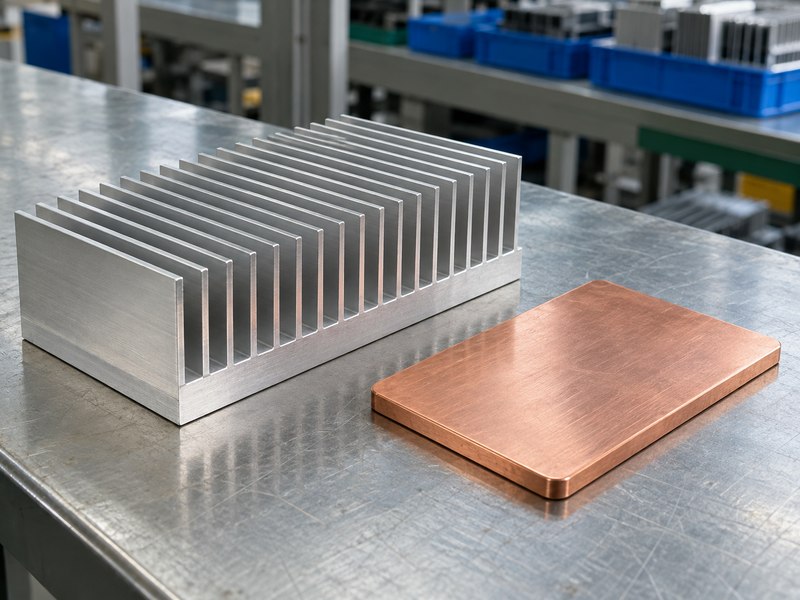
Choose the wear resistant radiator heat sink material around heat spreading, mass and manufacturing constraints. Aluminum supports lightweight integral fin structures and anodized surfaces. Copper can reduce spreading resistance under a concentrated source, although it adds mass and changes the joining and finishing choices. A material’s conductivity alone does not establish the assembly’s temperature.
Is the base or the air side limiting performance?
Check the location of the temperature drop. A hot spot beneath a small device may justify a copper spreader, heat pipe or vapor chamber. A nearly uniform hot fin field with inadequate airflow calls for work on convection. Replacing aluminum with copper in that situation can add weight without enough temperature reduction. For a mixed construction, specify the joint and test the assembled part. Contact resistance between materials and thermal expansion during cycling can affect the result, especially if a thin bonded layer carries the heat.
- Map temperatures near the source and across the base.
- Check support loads before adding a heavy spreader.
- Define corrosion protection where dissimilar metals meet.
Change the material where conduction limits the design.
| Construction | Useful capability | Review point |
|---|---|---|
| Integral aluminum | Low mass and repeatable fins | Source spreading |
| Copper spreader | Local heat spreading | Mass and attachment |
| Two-phase assembly | Heat transport across a footprint | Orientation and joint quality |
Request a comparison using the same footprint and cooling conditions.
4. Which surface finish protects the part without adding problems?
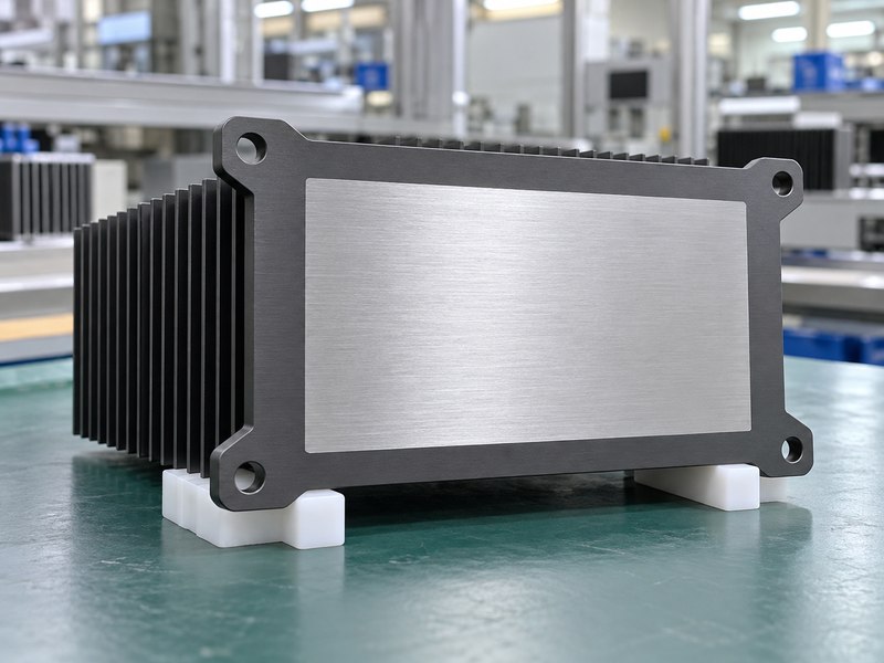
The wear resistant radiator heat sink finish should protect the surfaces that need it while respecting contact, grounding and dimensional requirements. Hard anodizing can improve aluminum’s abrasion resistance. It also creates an electrically insulating oxide layer and changes dimensions. Specify the coating thickness, masking and sealing condition instead of ordering a part by color alone.
Which surfaces should receive a separate callout?
Separate the exposed fins from the device mounting land. An oxide layer in the main conduction path can add resistance, while a masked land needs handling and corrosion protection appropriate to its environment. Grounding pads need their own electrical requirements; a bare patch alone does not define a reliable connection. Do not assume a thicker coating always improves the whole assembly. Verify fitted holes and threads after finishing, and confirm that the selected seal suits the required wear and corrosion performance.
- Mark thermal lands and electrical contact locations.
- Define coating thickness and allowable rack marks.
- Inspect finished dimensions against the final drawing.
Use a surface map rather than one blanket finish note.
| Surface | Requirement to define | Verification |
|---|---|---|
| Exposed fins | Finish and environment | Coverage and appearance |
| Device land | Flatness and interface condition | Inspection after finishing |
| Ground connection | Electrical contact performance | Assembly-level check |
Approve the treatment on a representative production sample.
5. How do fin spacing and airflow affect durability?
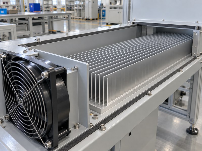
A wear resistant radiator heat sink needs fin spacing that supports both cooling and maintenance. Closely spaced fins add surface area but can restrict flow and retain debris. The installed operating point depends on the fan and the complete flow path, including filters, grilles and ducts. A free-air fan rating does not describe flow through the assembly.
Can your service team clean the fin field?
Check access before freezing the profile. A brush that fits between fins can still damage them if the approved cleaning method applies excessive force. A serviceable wear resistant radiator heat sink should provide a clear route for removing contamination without disturbing electronics or rubbing the device interface. Establish the cleaning method around actual contamination and site rules. If filters are part of the design, evaluate the pressure drop at the agreed replacement condition as well as when they are clean.
- Align straight fin channels with the intended flow.
- Limit bypass around the sides of the fin block.
- Leave clearance for the approved cleaning method.
Review cooling at the planned maintenance condition.
| Condition | What changes | Check |
|---|---|---|
| Clean inlet | Baseline resistance | Initial thermal test |
| Loaded filter | Available airflow | Service-limit test |
| Dust accumulation | Flow distribution | Representative contamination review |
A repeatable maintenance condition gives the thermal test a useful boundary.
6. How should you control mounting and interface wear?
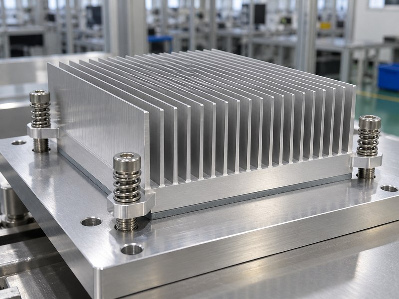
Control wear resistant radiator heat sink mounting by keeping clamp load stable and preventing motion at the thermal interface. A loose joint can change contact pressure or allow fretting. An overtightened joint can distort the base, package or PCB. Define the load path using the device supplier’s mechanical limits and the actual tolerance stack.
What should the assembly drawing include?
Check the full stack. Fastener torque alone does not guarantee a particular clamp force because thread and bearing friction vary. Springs, stops and supported brackets can help control movement, but their dimensions and working range still need calculation. Match the TIM to the gap and pressure instead of selecting it only by conductivity. Consider heat sink mounting hardware as part of the assembly design, including the tightening sequence and access needed during service. Keep vibration loads out of fragile device leads and unsupported board areas.
- Define fasteners, washers, springs and insulating parts.
- State the assembly sequence and allowed rework.
- Review preload after thermal and vibration exposure.
Preserve the interface through the product’s service conditions.
| Detail | Risk if omitted | Drawing requirement |
|---|---|---|
| Clamp range | Device overload or poor contact | Allowed force window |
| TIM gap | Excess interface resistance | Compressed thickness |
| Structural support | Board or joint movement | Defined load path |
Validate these details on the complete mounting stack.
7. Which manufacturing route fits your geometry?
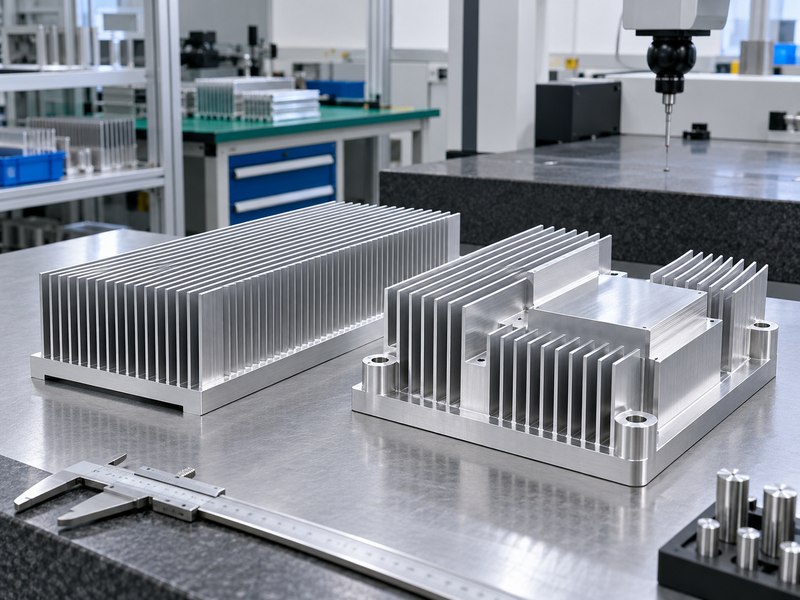
Choose the wear resistant radiator heat sink manufacturing route around the final geometry and production quantity. Extrusion suits a continuous cross-section with integral straight fins. CNC machining supports local pockets, steps and interfaces. Forging, skiving and assembled fins offer other geometry choices, each with process constraints that need a supplier review.
Which features deserve early manufacturing feedback?
Review the vulnerable details. Very thin, tall fins can be difficult to produce, handle and inspect even when a CAD model looks clear. Holes near fin roots may complicate tool access or weaken a local feature. A machined contact land can require a different datum strategy from the unfinished extrusion. Ask for comments on fin thickness, straightness, base flatness and finishing access before ordering tooling. Compare the complete route, including deburring, cleaning, masking, inspection and packaging, rather than a quoted raw profile alone.
- Identify functional surfaces and practical inspection datums.
- Define burr limits around contact and airflow areas.
- Approve a sample after all finishing operations.
Quote the finished, inspectable component.
| Route | Useful geometry | Review before order |
|---|---|---|
| Extrusion | Constant fin cross-section | Die feasibility and straightness |
| CNC machining | Local steps and contact lands | Tool access and cycle time |
| Assembled fins | Separate base and fin design | Joint integrity and handling |
Use the same finished requirements when comparing process quotations.
8. When should you consider a liquid cold plate?
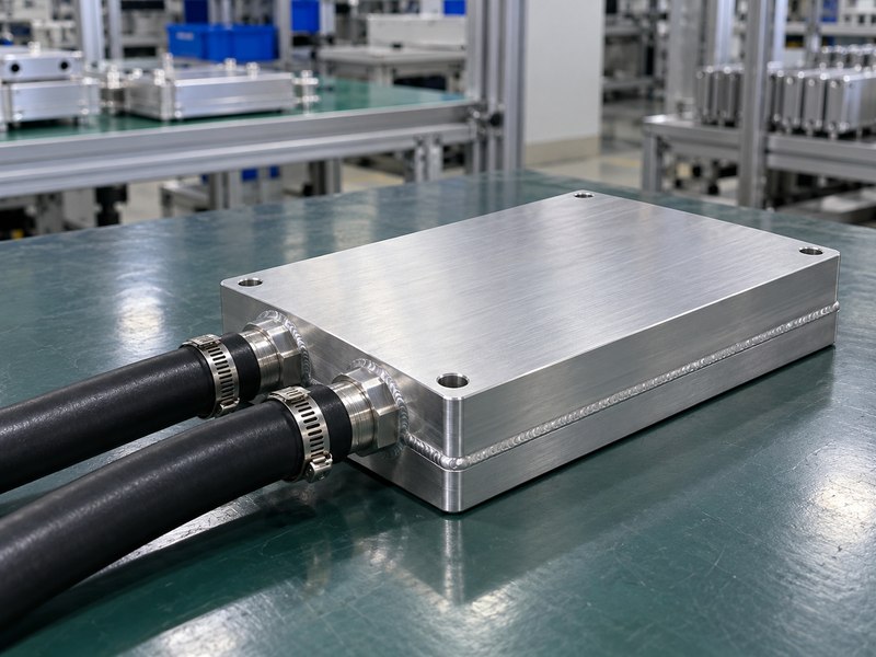
Consider a liquid cold plate when a wear resistant radiator heat sink cannot meet the temperature target within the available airflow and space. A cold plate moves heat into coolant, so it also needs a pump, heat rejection device and controlled fluid circuit. The decision must cover that complete system and its maintenance demands.
What changes when coolant enters the design?
Define the fluid circuit before choosing a plate. Coolant composition, temperature, flow and pressure affect materials and performance. Ports need compatible seals and enough space for assembly without loading the plate excessively. A mixed-metal circuit requires a corrosion strategy based on the selected coolant and supplier guidance. For a hybrid liquid-cooled heat sink, keep the liquid-cooled main load and air-cooled auxiliary loads explicit. Do not assume that adding ports to a finned base creates a validated cold plate.
- Specify operating pressure and leak acceptance criteria.
- Check coolant compatibility across the whole circuit.
- Plan draining, filtration and service access.
Evaluate liquid cooling as a system-level change.
| System item | Requirement | Evidence |
|---|---|---|
| Cold plate | Thermal and pressure performance | Agreed test results |
| Fluid circuit | Compatible materials and coolant | Approved component list |
| Heat rejection | Operation at worst inlet conditions | Complete system test |
Keep air and liquid options on matching thermal boundaries.
9. What tests should confirm the finished assembly?
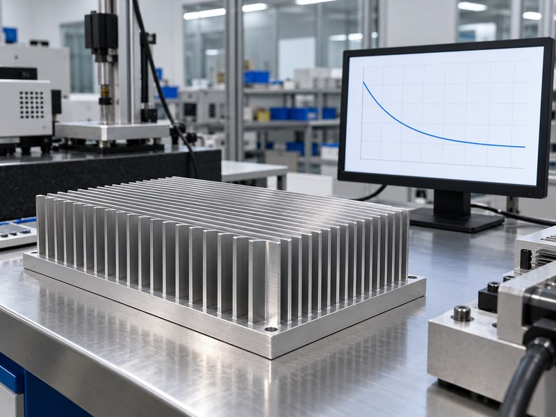
Confirm the wear resistant radiator heat sink through thermal testing and the environmental checks relevant to its installation. A coating test alone cannot establish fin strength or assembly temperature. A thermal test on an uncoated prototype cannot establish the final finished part’s performance. Record the build state and test method so later batches can be compared fairly.
How should you compare results before and after exposure?
Hold the measurement conditions constant. Use the same heat input, sensor locations, TIM, clamp method, orientation and cooling conditions. Measure inlet temperature close enough to represent the supplied air without placing the sensor in a disturbed hot zone. For a wear trial, define the counterface, load, motion and number of cycles. Inspect the contact land and fins afterward, then repeat the thermal test if the exposure could affect heat flow. Agree on pass limits before testing to avoid judging samples by appearance alone.
- Document sensor placement and measurement uncertainty.
- Identify samples by material, finish and revision.
- Separate illustrative curves from measured acceptance records.
A useful test connects a defined exposure to a functional limit.
| Check | Control variable | Acceptance basis |
|---|---|---|
| Thermal performance | Heat input and cooling condition | Device temperature limit |
| Wear exposure | Load, counterface and cycles | Agreed functional criteria |
| Post-test inspection | Drawing revision | Dimensions and damage limits |
Retain the conditions alongside the results.
10. What should you send with a supplier enquiry?
Send the wear resistant radiator heat sink supplier a drawing, operating conditions and acceptance plan. Include the heat-source footprint, losses, temperature limit, mounting envelope and expected exposures. A quotation can then address the finished assembly instead of leaving the finish, tolerances or validation work for a later discussion.
How can you make sample approval useful for production?
Close the open details before approval. Record the agreed material and temper, surface map, interface requirements, inspection points and packaging. Separate sample testing from routine batch checks so both sides understand the scope. If a supplier proposes a different profile, compare its thermal and mechanical evidence against the same requirements. Ask for controlled revisions when the material, finish or manufacturing route changes. Share these inputs when you contact us for a drawing review and a manufacturing proposal matched to your equipment.
- Supply CAD with a controlled drawing revision.
- State quantities, delivery stages and quality records.
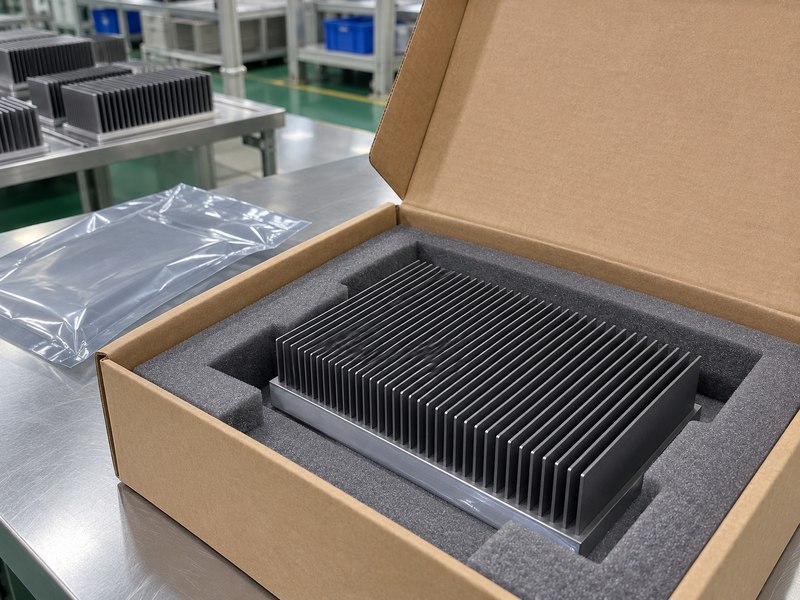
- Agree on protection for fins and contact faces during shipment.
Approve a repeatable specification as well as a sample.
| Enquiry item | Detail to include | Purchasing benefit |
|---|---|---|
| Thermal brief | Losses, limits and cooling conditions | Comparable proposals |
| Mechanical brief | Datums, mounting and finish map | Fewer fit ambiguities |
| Acceptance plan | Sample and batch checks | Clear release requirements |
Request the agreed drawing and test scope with the quotation.
FAQ
Q1: Can I specify wear resistance without a coating thickness?
Only if another agreed specification defines it. Otherwise, the supplier lacks a measurable requirement for the finished surface.
Q2: What’s the best finish for a dusty industrial cabinet?
It depends on the contaminants, cleaning method and corrosion exposure. Check airflow and maintenance access alongside the surface finish.
Q3: How do I know if a scratch affects cooling?
Inspect its location and depth. Damage on the contact face, a bent fin or lost coating in a corrosive environment needs a functional review.
Q4: Can I replace an aluminum sink with copper directly?
Only after checking mass, mounting, geometry, interfaces and environment. Higher conductivity alone does not establish equivalent assembly performance.
Q5: Should I test the coated production sample?
Yes. Test a representative finished assembly with the intended TIM, mounting method and cooling conditions before approving the design.