
Choose a heat sink for welding stainless steel that contacts the joint closely, leaves room for the weld and can absorb repeated heat pulses. A copper chill bar can help control local heating, but it cannot correct poor fit-up or an unsuitable weld procedure. Design the fixture around the actual joint.
1. Which heat sink for welding stainless steel should you use?
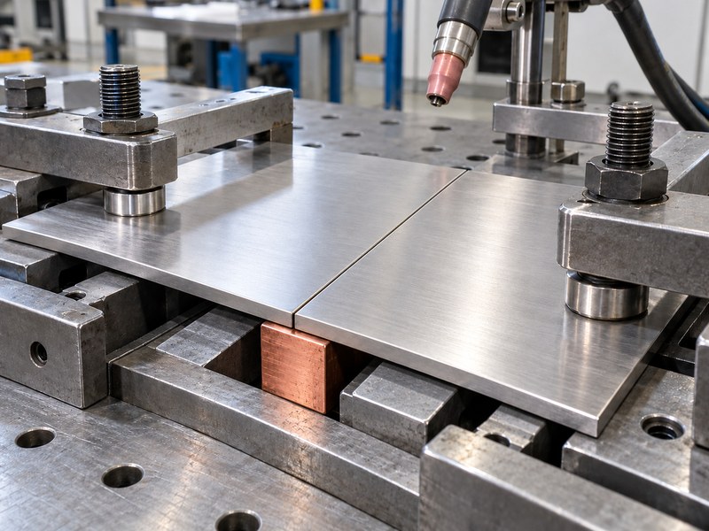
Use a heat sink for welding stainless steel that matches the workpiece shape and required weld access. A flat copper bar suits some straight joints, while a shaped insert may suit a corner or curved panel. Contact area and repeatable placement matter more than choosing the heaviest available block.
Decide which part of the assembly needs cooling
The fixture discussed here removes heat from the workpiece near the joint. A cold plate for welding equipment serves a different duty when it cools power electronics inside the welding machine. Keep those two requirements separate in drawings and purchase orders.
A shaped heat sink for welding stainless steel should locate consistently without forcing the joint out of position. Include a clear removal route after cooling, especially when the weld can trap the tooling.
- Identify the joint face that can contact the chill.
- Reserve torch, filler and inspection access before adding clamps.
- Define how the operator locates and removes the tooling.
| Joint feature | Possible chill arrangement | Check |
|---|---|---|
| Straight butt joint | Flat backing bar | Close contact and root access |
| Outside corner | Shaped copper insert | No trapped tooling |
| Curved panel | Matching contoured support | Fit without forced distortion |
Select the contact geometry before deciding on bar length or production quantity.
2. Which heat sink for welding stainless steel material works?
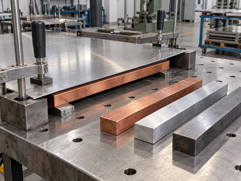
A heat sink for welding stainless steel commonly uses a conductive material such as copper when the fixture must draw heat from a small joint area. Material selection must also account for contamination, wear, cost and the chance of contact with the arc or molten weld.
Use mass and conductivity for different jobs
Conductivity affects how quickly heat moves away from the contact area. Heat capacity and mass affect how much the fixture temperature rises during a pulse. A large poorly contacting block can leave the immediate joint hot even though much of the block remains cool.
For an illustrative storage calculation, take a 0.25 kg copper bar and assume a specific heat of 385 J/(kg·K). A 30 K rise stores about 2.9 kJ; this calculation excludes heat lost to air or conducted into other tooling.
- Use an identified material and a clean, suitable contact surface.
- Avoid treating decorative plating as proof of the underlying alloy.
- Keep the intended weld path clear of accidental tooling contact.
| Property | What it affects | What it cannot establish alone |
|---|---|---|
| Conductivity | Heat spreading within the chill | Contact quality |
| Heat capacity | Temperature rise during a pulse | Recovery between cycles |
| Hardness and condition | Wear and handling | Weld suitability |
Evaluate both the initial heat pulse and the repeated production cycle.
3. How should a heat sink for welding stainless steel contact?
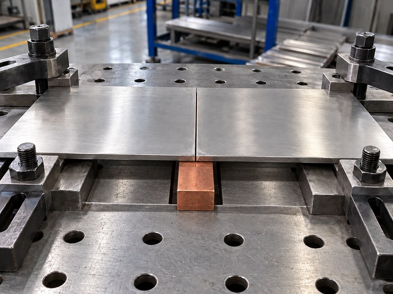
A heat sink for welding stainless steel should contact the intended surface closely and consistently without changing the joint fit-up. An air gap restricts heat transfer and can make the same fixture behave differently from one part to the next. Surface shape and clamp position control that gap.
Support the joint without pulling it into a new shape
Check the fit with the sheet resting naturally in the fixture. If substantial force is needed to flatten it, you may be storing mechanical strain that reappears after release. A conforming chill surface and a sensible locating scheme can reduce that dependence on clamp force.
Review heat sink for welding stainless steel retention as part of the fixture design. Clamps should resist movement and preserve access while keeping the workpiece within its accepted position and contact condition.
- Remove burrs and debris from the contact region.
- Place clamps where they maintain contact near the joint.
- Check that thermal expansion will not lock the workpiece against its locators.
| Contact problem | Likely effect | Fixture change to review |
|---|---|---|
| Local air gap | Uneven heat extraction | Matching support contour |
| Excess clamp force | Strain or surface damage | Better contact geometry |
| Poor locating | Cycle-to-cycle variation | Repeatable stops and datums |
Record the contact and clamping method with the qualified setup.
4. Does a heat sink for welding stainless steel need a groove?
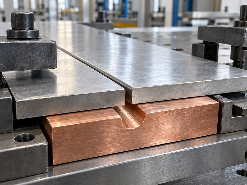
A heat sink for welding stainless steel may need a clearance groove when the weld root requires space or a specific backing arrangement. Groove shape affects support, root access and heat extraction. A generic flat bar pressed against every joint can interfere with the intended weld geometry.
Define the root condition with the weld requirement
Where backing gas is required, the fixture must allow the specified shielding arrangement and flow path. A copper backing surface does not automatically replace that requirement. Its location also needs to avoid unintended melting, arc contact or transfer of tooling material into the weld.
Match the groove, joint preparation and backing method through the applicable procedure and trial coupons. Inspect both the weld face and root rather than selecting a groove because it produced a smooth-looking face on one sample.
- State the required root profile and permitted backing arrangement.
- Keep gas paths clear where the procedure requires them.
- Provide access for root inspection and removal of residue.
| Joint requirement | Tooling implication | Validation |
|---|---|---|
| Controlled root shape | Suitable relief geometry | Root inspection |
| Backing gas | Defined gas path and seals | Procedure-specific check |
| Removable backing | Accessible release route | Trial removal after cooling |
Treat a groove as a joint-design feature rather than an automatic improvement.
5. Can a heat sink for welding stainless steel stop distortion?
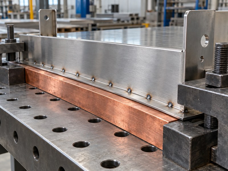
A heat sink for welding stainless steel can help manage distortion, but its effect depends on joint fit-up, restraint and the weld sequence. Local cooling changes temperature gradients. It does not remove the contraction associated with a weld or guarantee the dimensions after fixture release.
Review the whole sequence
Use the accepted weld size and sequence rather than adding extra weld metal as a precaution. Tack placement, restraint and the order of weld segments should suit the part and its procedure. A sequence that works on a short coupon can behave differently on a large panel.
A heat sink for welding stainless steel may need multiple contact inserts so heat extraction remains consistent as the weld progresses. Check dimensions after the assembly has cooled and been released from the fixture.
- Confirm the joint gap and alignment before welding.
- Use the procedure’s weld size and permitted sequencing options.
- Measure the free-state part rather than the restrained part alone.
| Control | Addresses | Check after welding |
|---|---|---|
| Fit-up | Unnecessary fill and variation | Joint consistency |
| Sequence | Uneven heat accumulation | Overall distortion |
| Chill contact | Local temperature distribution | Released dimensions |
Accept a distortion-control method from repeatable results on representative parts.
6. How does a heat sink for welding stainless steel affect TIG?
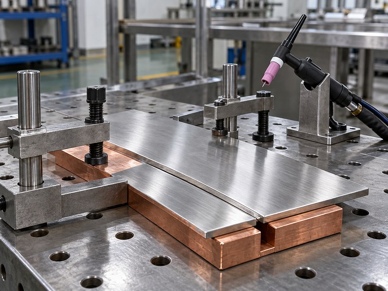
A heat sink for welding stainless steel can change how quickly the joint absorbs and redistributes energy during TIG welding. The accepted setup may require different settings from a similar joint without a chill. Those settings need to remain within the qualified procedure and produce the required weld.
Distinguish arc energy from heat removed by the chill
For a simplified steady-arc example, 10 V, 60 A and 120 mm/min correspond to 300 J/mm of electrical arc energy. Net heat delivered to the workpiece also depends on process efficiency, while a chill changes where heat goes afterward. The chill does not reduce the power supply’s energy input by itself.
Pulsed settings add peak current, background current and timing to the picture. Compare the actual setup rather than assuming a higher pulse frequency always lowers distortion or improves corrosion resistance. Published sheet-welding guidance also discusses backing and chill bars alongside other heat-control methods.
- Record the relevant machine settings and travel conditions.
- Check fusion and root condition after changing the fixture.
- Keep torch access and shielding consistent during trials.
| Changed variable | Possible consequence | Required check |
|---|---|---|
| Added chill contact | Different local cooling | Fusion and geometry |
| Pulse settings | Different energy delivery | Procedure compliance and weld quality |
| Travel conditions | Different energy per length | Representative coupon results |
Validate settings and tooling together because either can change the weld result.
7. How clean must a heat sink for welding stainless steel be?
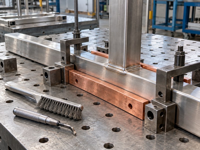
A heat sink for welding stainless steel should be clean enough to avoid introducing contamination or disrupting contact at the joint. Residue, embedded particles and damaged surfaces can affect both the fixture’s heat path and the finished weld area. Cleaning needs a defined method rather than an occasional visual wipe.
Keep welding tooling separate from interface products
Electronic thermal pads, greases and adhesive interfaces belong to different operating conditions. Do not put them between a weld joint and its chill as a shortcut for improving contact. Their behavior under welding conditions must not be assumed from an electronics datasheet.
Include the heat sink for welding stainless steel tooling in the workshop’s cleaning and handling review. Separate storage and suitable dedicated tools can help preserve the accepted condition between batches.
- Use cleaning methods compatible with the specified material and process.
- Inspect contact surfaces for pickup, dents and embedded debris.
- Define when the insert must be cleaned, reworked or replaced.
| Inspection point | Look for | Response |
|---|---|---|
| Contact surface | Deposits or damage | Clean or restore the approved surface |
| Fixture storage | Cross-contamination | Separate and protect tooling |
| Joint region | Residue and foreign material | Prepare before assembly |
Make the cleaning condition part of the production instruction so operators can reproduce it.
8. How should a heat sink for welding stainless steel fit corners?
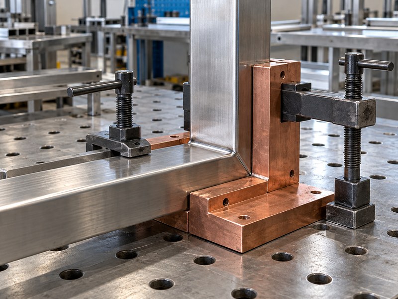
A heat sink for welding stainless steel should fit a corner without blocking torch access or becoming trapped after welding. The contact insert needs enough support to remain stable, while the fixture must permit the workpiece to expand and then release. Split or removable inserts can help when a solid block cannot be withdrawn.
Check the entire assembly and removal sequence
Model the torch approach, clamps, locators and finished weld before making the tooling. A fixture that assembles easily may still require damaging force to remove once the part contracts. Include access for inspection so a hidden root condition does not escape the trial review.
For repeated work, separate a wear insert from the larger support where practical. That can allow replacement of a damaged contact surface without rebuilding the entire fixture, provided the replacement preserves the accepted thermal and locating conditions.
- Check access throughout the weld path, not at one static position.
- Provide a controlled removal route after cooling.
- Identify replaceable surfaces and their locating features.
| Corner-fixture feature | Purpose | Design check |
|---|---|---|
| Shaped insert | Close local contact | Fit without forcing the joint |
| Removable segment | Release after contraction | Withdrawal clearance |
| Replaceable contact | Manage wear | Repeatable position and heat path |
Trial the complete loading-to-unloading sequence before calling the fixture production-ready.
9. How do you test a heat sink for welding stainless steel?
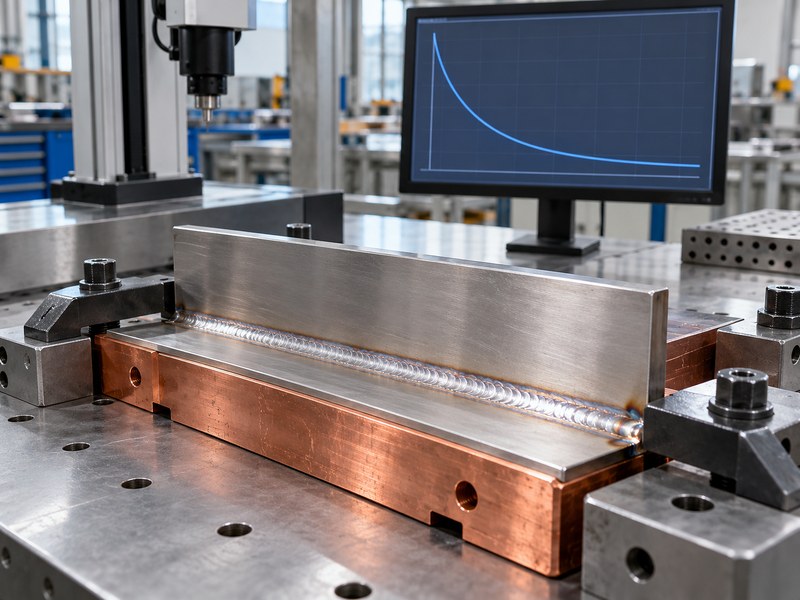
Test a heat sink for welding stainless steel on representative joints and repeated cycles, then inspect the weld and the released part. Record the fixture’s temperature before each cycle because a warming chill can behave differently after several parts. One cold-start coupon does not describe sustained production.
Watch recovery between cycles
Using the earlier illustrative 0.25 kg copper bar, a retained 1 kJ pulse would raise its average temperature by about 10.4 K if losses were ignored. Real fixtures exchange heat with their supports and surroundings, so measure the cycle rather than extending that estimate indefinitely.
The heat sink for welding stainless steel trial should include the production contact surfaces and clamping arrangement. Inspect dimensions, root condition and any procedure-required properties after the fixture reaches its repeated operating condition.
- Record starting temperature, cycle duration and recovery time.
- Compare dimensional results after cooling and release.
- Include checks required by the material and weld procedure.
| Trial stage | Record | What it reveals |
|---|---|---|
| Cold start | Initial fixture condition | Initial-cycle behavior |
| Repeated cycles | Temperature and timing | Heat accumulation |
| Released part | Weld and dimensions | Actual accepted product condition |
Set the acceptance criteria before the trial so a smooth weld face cannot become the only measure.
10. What must a heat sink for welding stainless steel RFQ include?
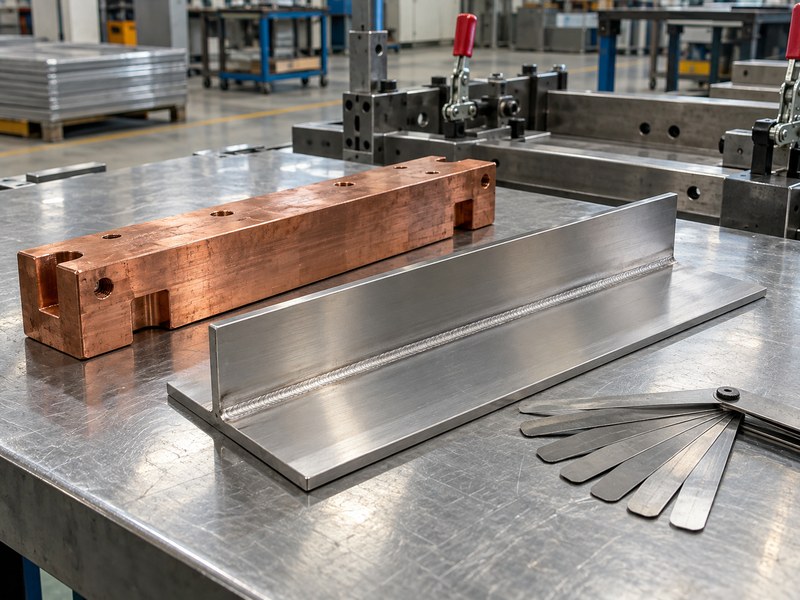
A heat sink for welding stainless steel RFQ should include joint geometry, material, access, cycle timing and acceptance requirements. The tooling supplier needs to understand whether the part requires backing, heat extraction, locating support or several of those functions. A sketch of the outer block alone leaves those decisions unresolved.
Request a fixture review before ordering a batch
Provide the intended weld procedure, workpiece tolerances and photographs or models of the surrounding assembly. Identify replaceable inserts, cleaning access and the sample trial needed before production. Ask the supplier to flag geometry that could trap the part or interfere with the weld path.
Share the drawing and cooling requirement when you contact us. We can discuss relevant machined thermal components and distinguish workpiece tooling from the heat sinks or cold plates needed inside the welding equipment.
- Define the contact region and the permitted backing arrangement.
- State production timing and expected tooling service conditions.
- Agree on a representative trial and the records to retain.
| RFQ information | Include | Decision it supports |
|---|---|---|
| Workpiece | Material, joint and tolerances | Contact geometry |
| Process | Procedure, access and cycle | Fixture suitability |
| Acceptance | Weld checks and released dimensions | Trial approval |
Order the fixture against the reviewed setup and acceptance record.
FAQ
Q1: Can I use copper as a heat sink for stainless welding?
Yes, when the joint and procedure permit the backing arrangement. Check contact, weld access and the risk of unintended tooling contact rather than relying on conductivity alone.
Q2: Will a chill bar remove all distortion?
No. Fit-up, weld size, restraint and sequencing still affect distortion. Measure the cooled part after release because the fixture can temporarily hide movement.
Q3: Can I use a chill bar instead of backing gas?
Only if the applicable weld requirement permits that arrangement. A backing bar does not automatically provide the shielding or root condition required for a particular stainless joint.
Q4: How do I know whether the chill is overheating?
Record its temperature across repeated production cycles and compare the weld and dimensional results. A successful cold-start sample can conceal a recovery problem later in the batch.
Q5: Can I reuse the same fixture for a different stainless grade?
Only after reviewing the material, procedure and acceptance requirements. The same shape does not establish equivalent weld behavior or the correct cooling conditions.